
Brief introduction about NSX-T Multi Site:
- Provides overlay networking which spans multiple locations.
- Consistent security using NSX Distributed Firewall in cases where the VM moves to another location. There is no Distributed Firewall configuration that needs to be updated in NSX when VM moves to other location.
- NSX use cases like logical switching, logical routing, distributed firewall can be used. Please refer to NSX multi location guide for complete list of supported features based on the NSX release.
- Single NSX manager instance is used to configure NSX on servers in multiple locations and to deploy NSX edges (primarily for North South traffic but NSX edges can also be used for services on Tier 1 Gateway such as gateway firewall, NAT).
- Single pane of glass is provided by NSX manager which controls networking and security centrally for multiple locations.
- Scale limits are limited to scale of 1 NSX-T Manager cluster.
- Jumbo MTU is required cross locations because TEP interface on server in location 1 will establish tunnel with TEP interface on server in location 2. So cross location tunnels will be there.
Note: This lab considers/addresses one of the potential use cases of NSX Multi-Site. Please refer to NSX Multi location design guide for complete details about NSX Multi-Site
Physical Networking/Underlay setup in this lab:
This lab setup considers enough bandwidth between availability zones AZ1 and AZ2 so as to not cause network link congestion; consider customer-owned, multiple fibre links between AZ1 and AZ2.
Also from a latency perspective, the latency between AZ1 and AZ2 is less than 10 ms.
Physical network underlay is able to stretch VLANs between AZ1 and AZ2. Using this management VLAN for NSX manager will be stretched so as to utilize cluster VIP feature on NSX manager.
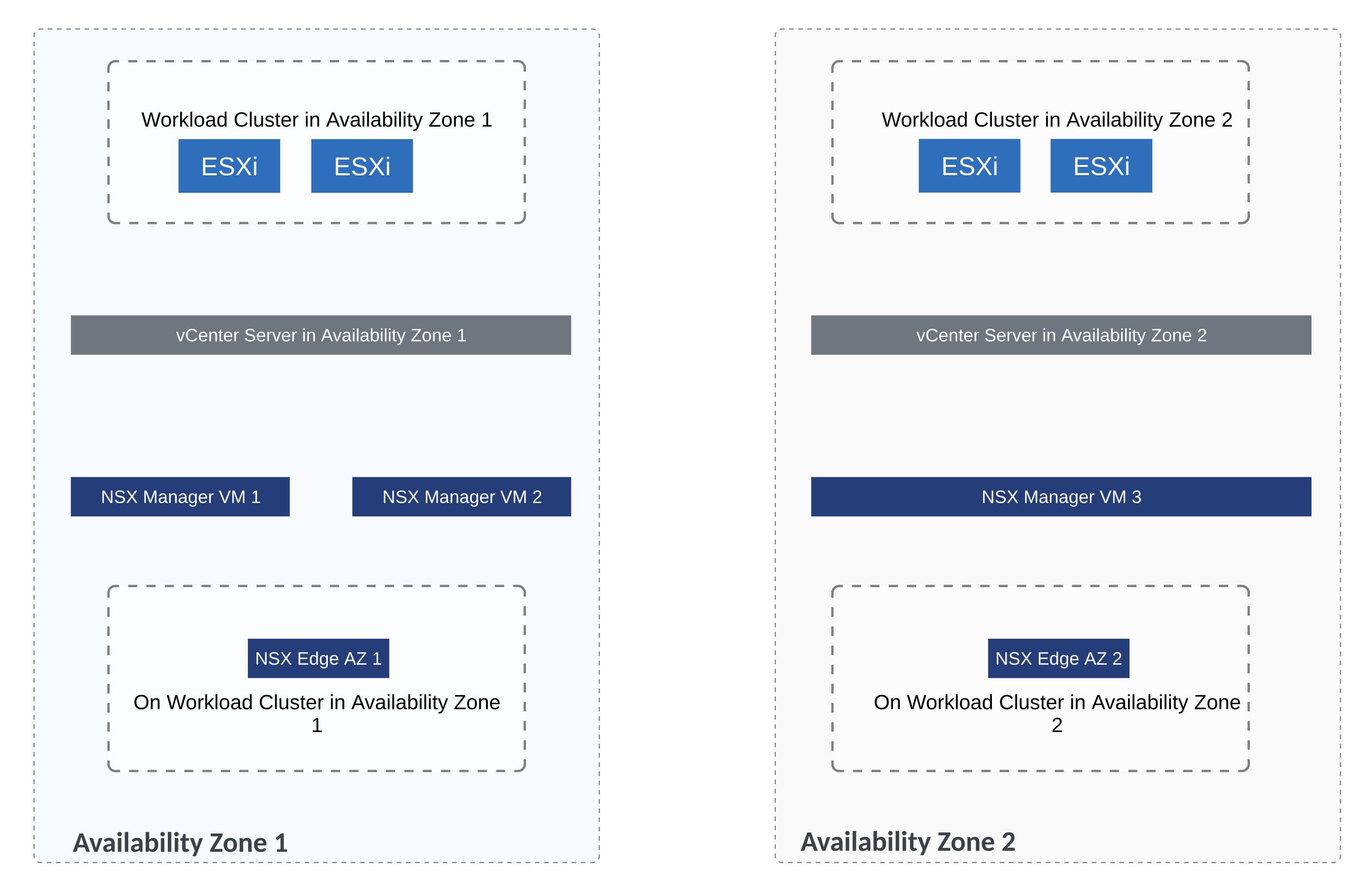
vSphere Setup
This custom use case has vcenter server in each location. So vcenter server in AZ1 and another vcenter server in AZ2. There are no stretched vSphere clusters in this lab environment.

Compute Cluster 1 is under the vcenter server in Mumbai location. Likewise there is compute cluster under the vcenter server in Bangalore location.
Note: Compute Cluster 2 in Mumbai location can be ignored for now and this cluster will not be prepared for NSX.
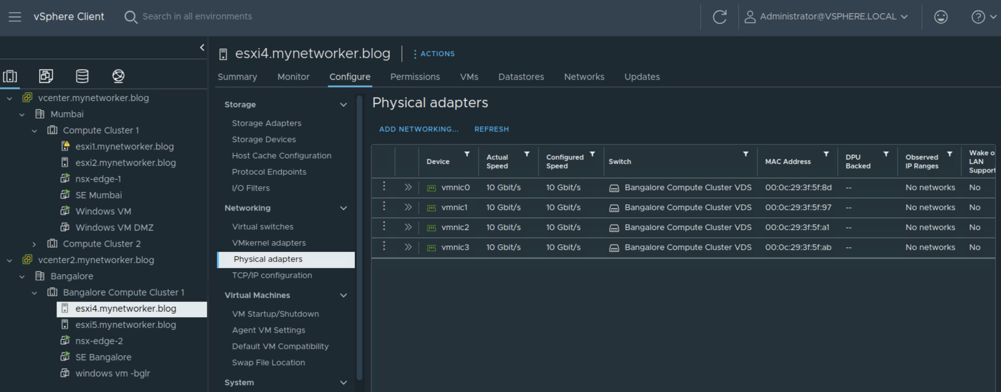
Single VDS on a per cluster basis is used.
NSX Fabric Setup
Single NSX manager instance is used in this setup and all the servers in AZ1 and AZ2 are NSX prepared using this single NSX instance.

Using the above connectivity, all NSX traffic remains on uplinks 3 and 4 of the VDS.

Below are the steps related to NSX Multi Site configuration which I used in this lab setup.

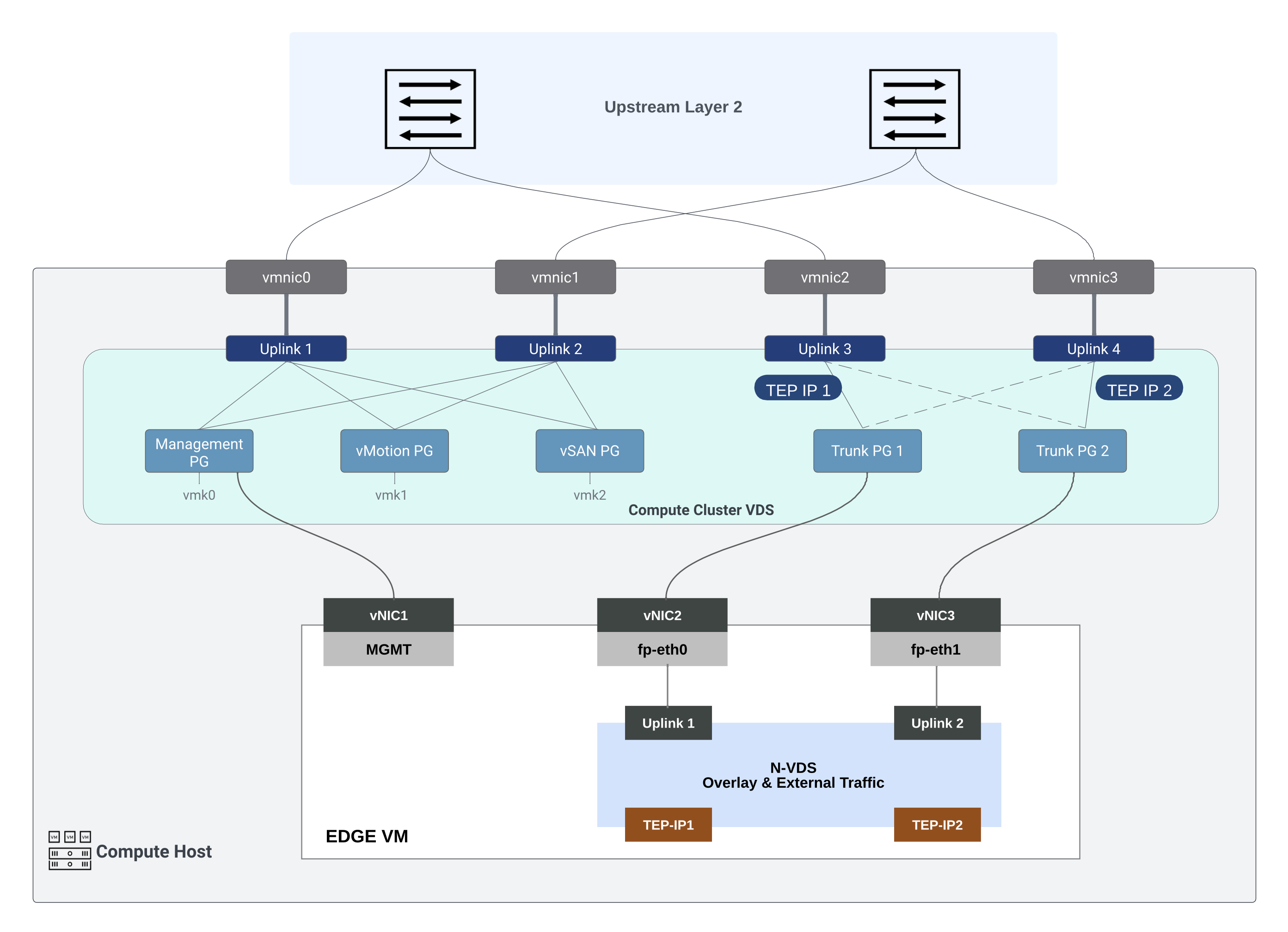
Uplink profile is created for host transport nodes/servers and I am using VLAN 2 as VLAN ID for Host Overlay Network.
Load Balance source teaming policy is used in this uplink profile for NSX overlay traffic.

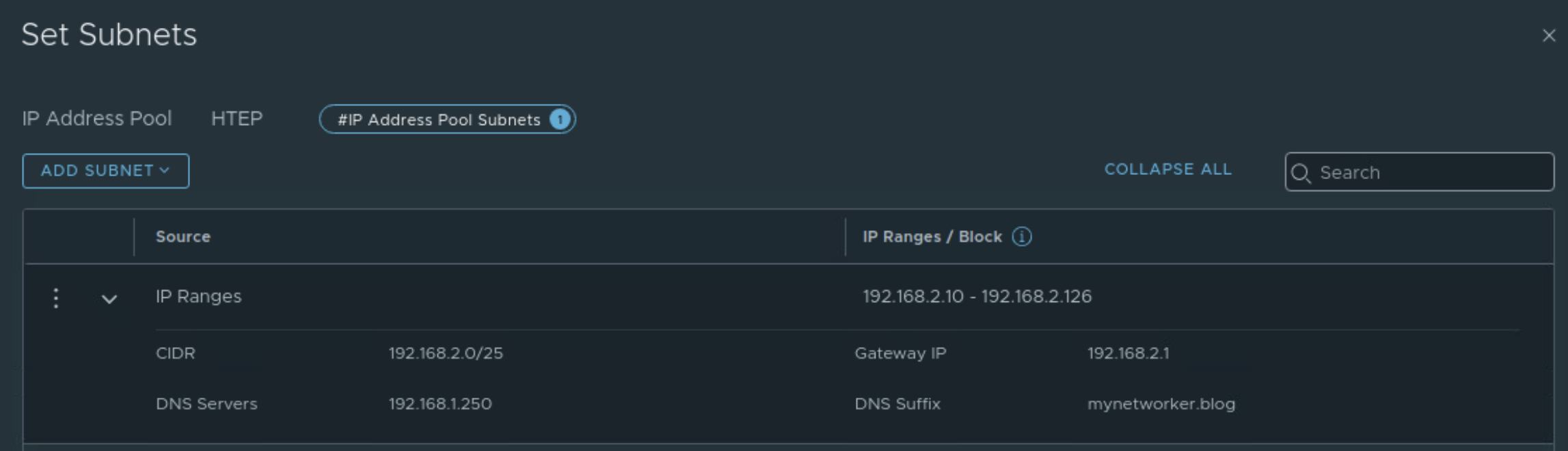
TEP pool is created for servers. VLAN corresponding to tunnel end points is stretched between AZ1 and AZ2 in this setup.
Next two transport node profiles are created corresponding to the two VDS’ under different vcenter servers. These transport node profiles are used to prepare appropriate vSphere clusters for NSX.
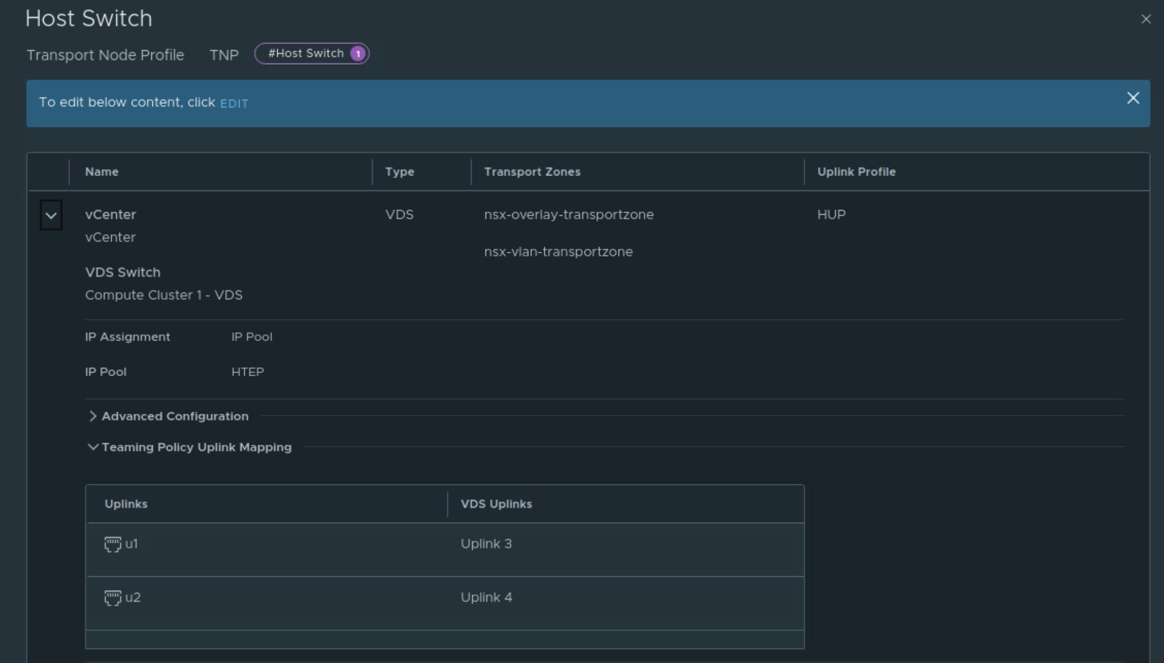
Uplink 3 and Uplink 4 of the VDS are used for NSX overlay traffic.
Similarly, transport node profile named ‘TNP Bangalore’ is created.

Using these transport node profiles, the servers in AZ1 and AZ2 are prepared for NSX.

Edge deployment:
1st NSX edge will be deployed on workload cluster of AZ1
And the 2nd NSX edge will be deployed on workload cluster of AZ2
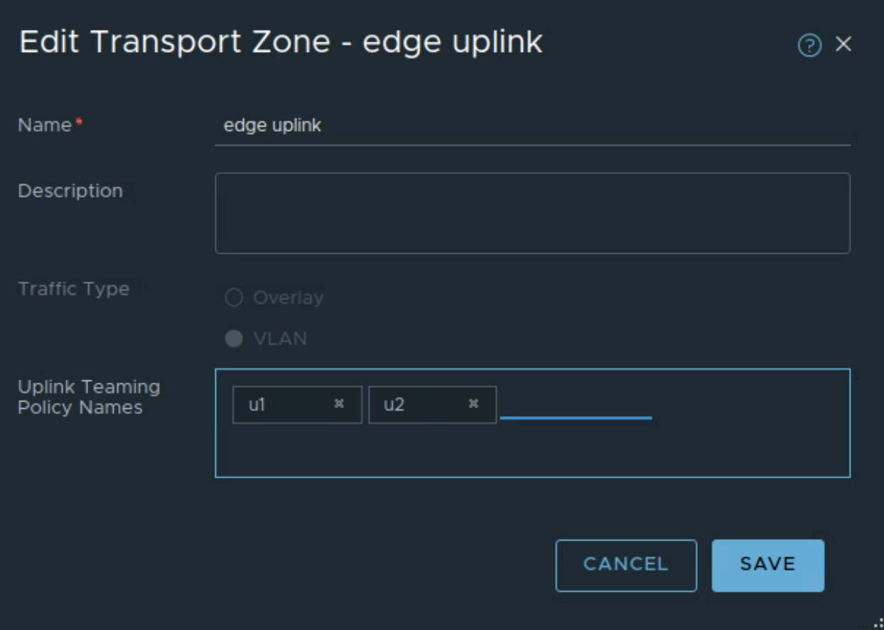
Named teaming policies will be used to pin VLAN traffic to appropriate trunk port group on upstream VDS. Edge uplink profile is created with appropriate VLAN ID corresponding to edge overlay traffic and with named teaming policies. u1 and u2 in figure below are additional named teaming policies.

The named teaming policies need to be mapped to edge uplink VLAN transport zone which is used to establish upstream VLAN connectivity towards L3 physical devices.
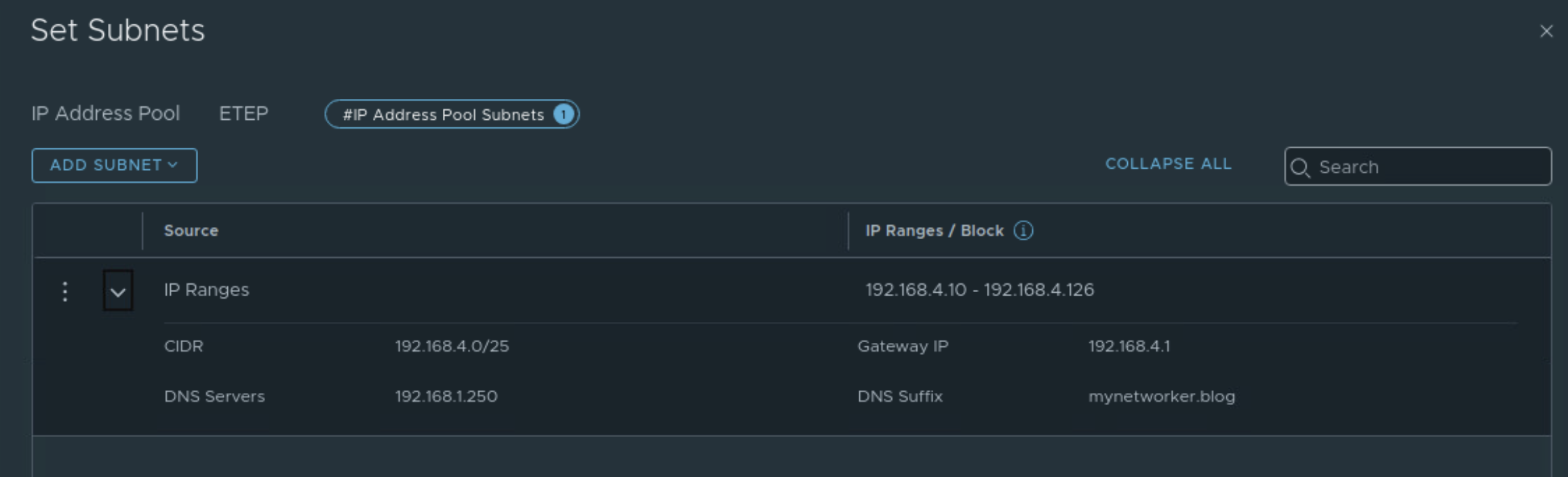
TEP pool for NSX edges is configured. This VLAN for NSX edge TEPs is again stretched between AZ1 and AZ2.
Next edges are deployed from NSX UI.
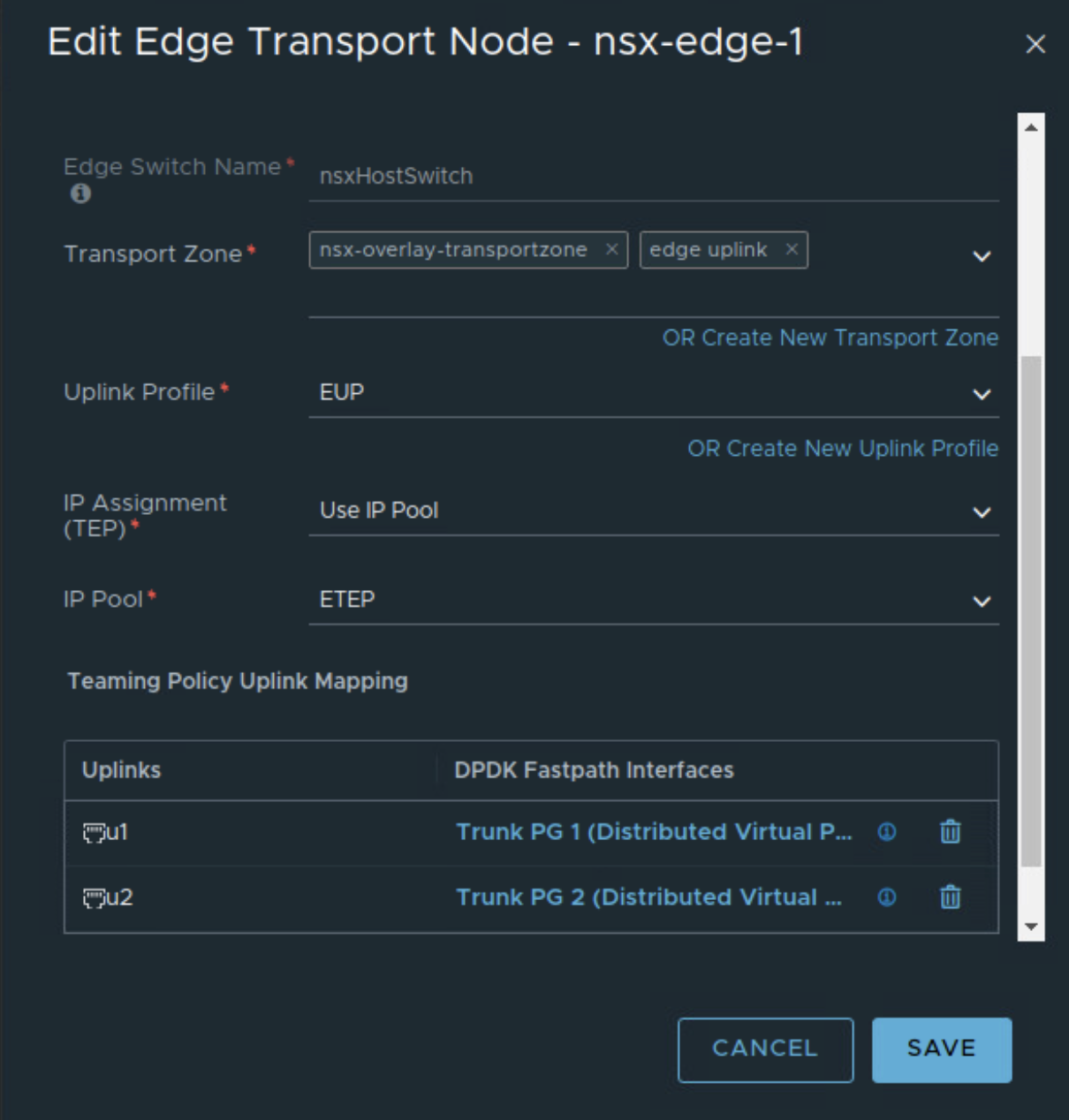
This NSX edge is connected to trunk port groups on upstream VDS with the teaming policies as below
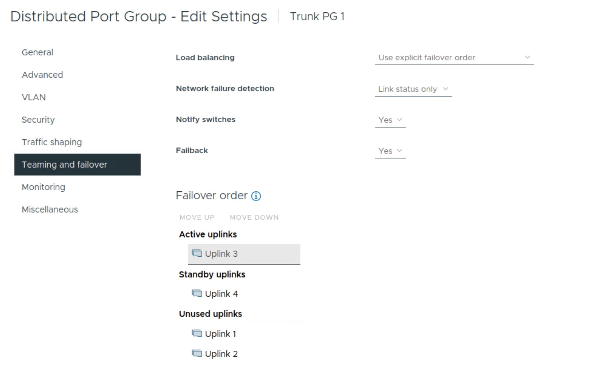
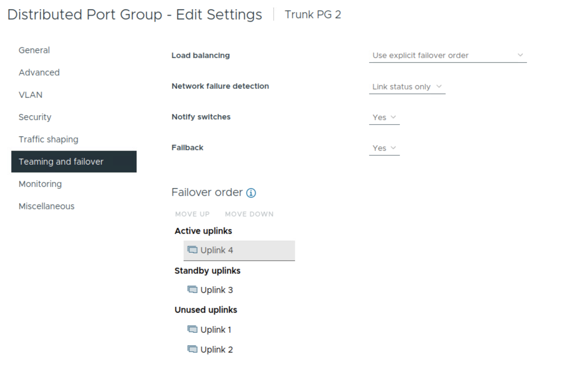
Notice that uplinks 3 and 4 on the VDS are used so these uplinks will be used for edge overlay and edge uplink VLAN traffic.
Similarly 2nd NSX edge is deployed and configured for NSX.

NSX edge cluster is created using the two deployed NSX edges.

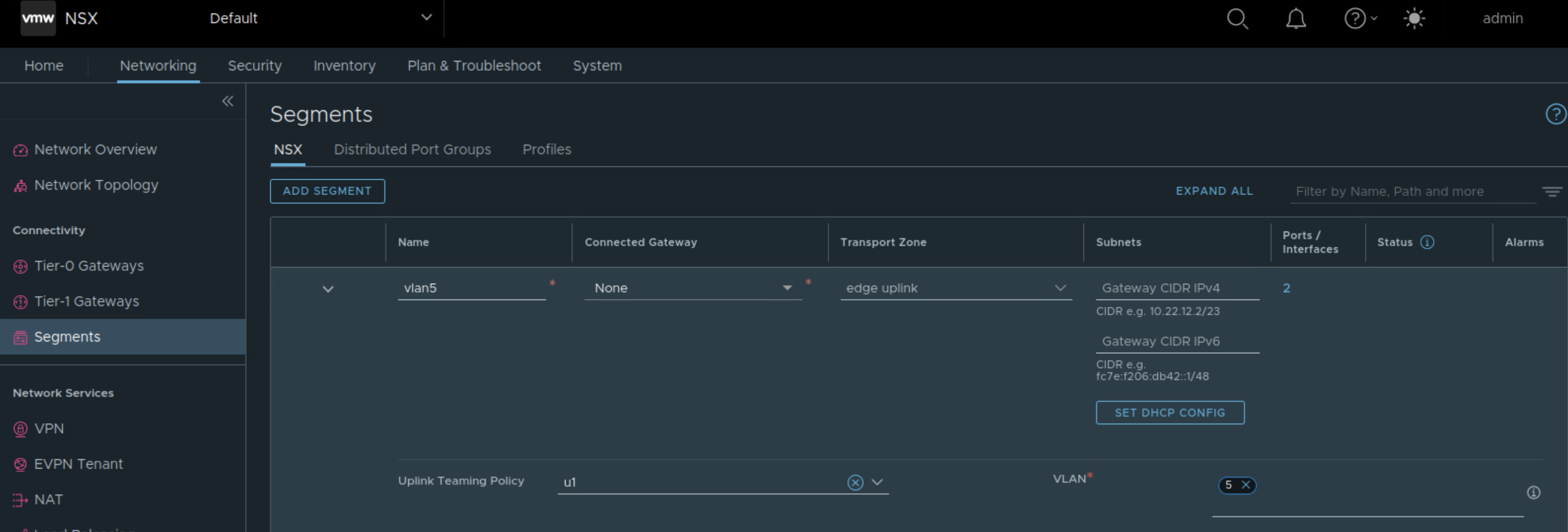
Tier 0 Gateway needs uplink segments, so those need to be created. Here the named teaming policy is referenced while creating VLAN segment for edge uplink.

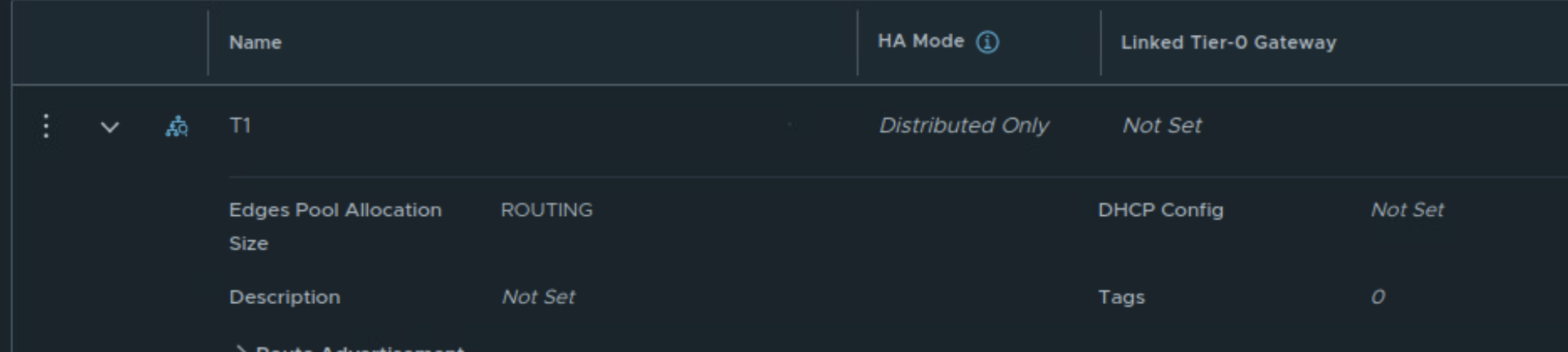
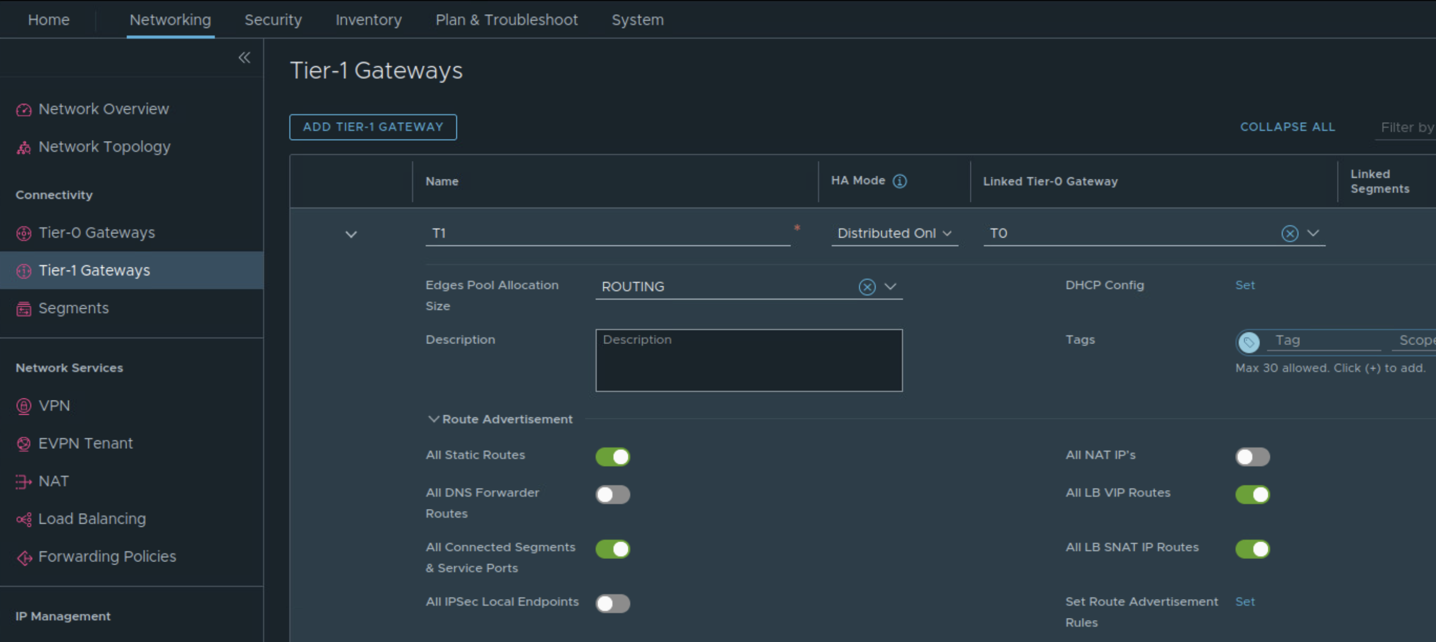
Next create DR only Tier 1 Gateway
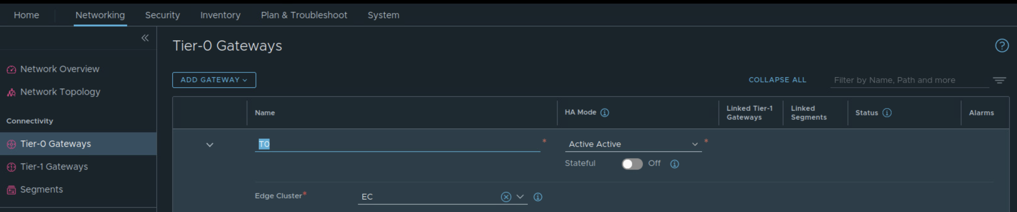
Create Tier 0 Gateway in Active-Active availability mode, map the edge cluster created earlier on this Tier 0 Gateway.
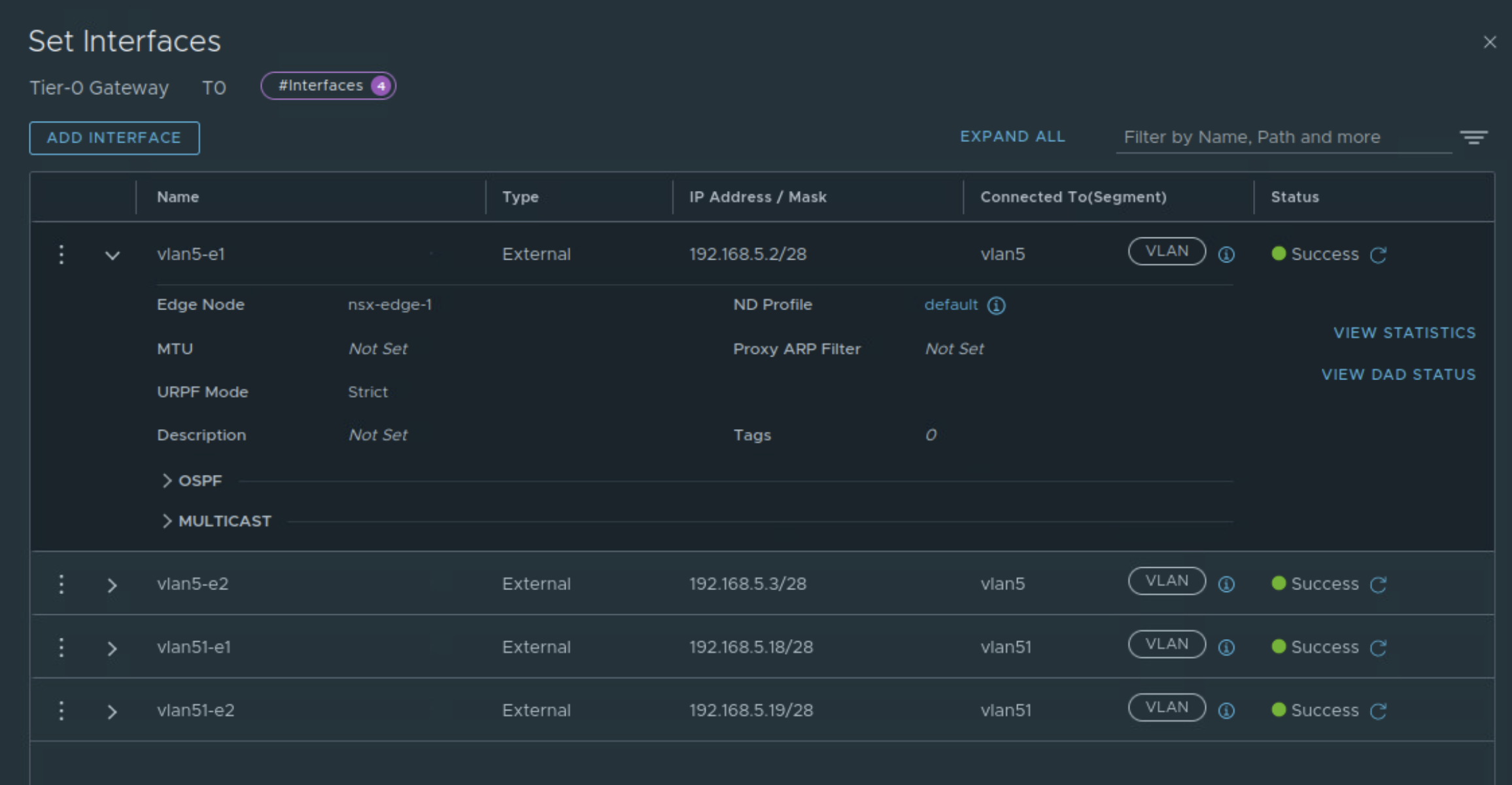
While creating interfaces on Tier 0 Gateway, appropriate VLAN segments are referenced (those with named teaming policy).
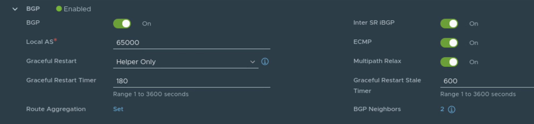
BGP is configured on Tier 0 Gateway

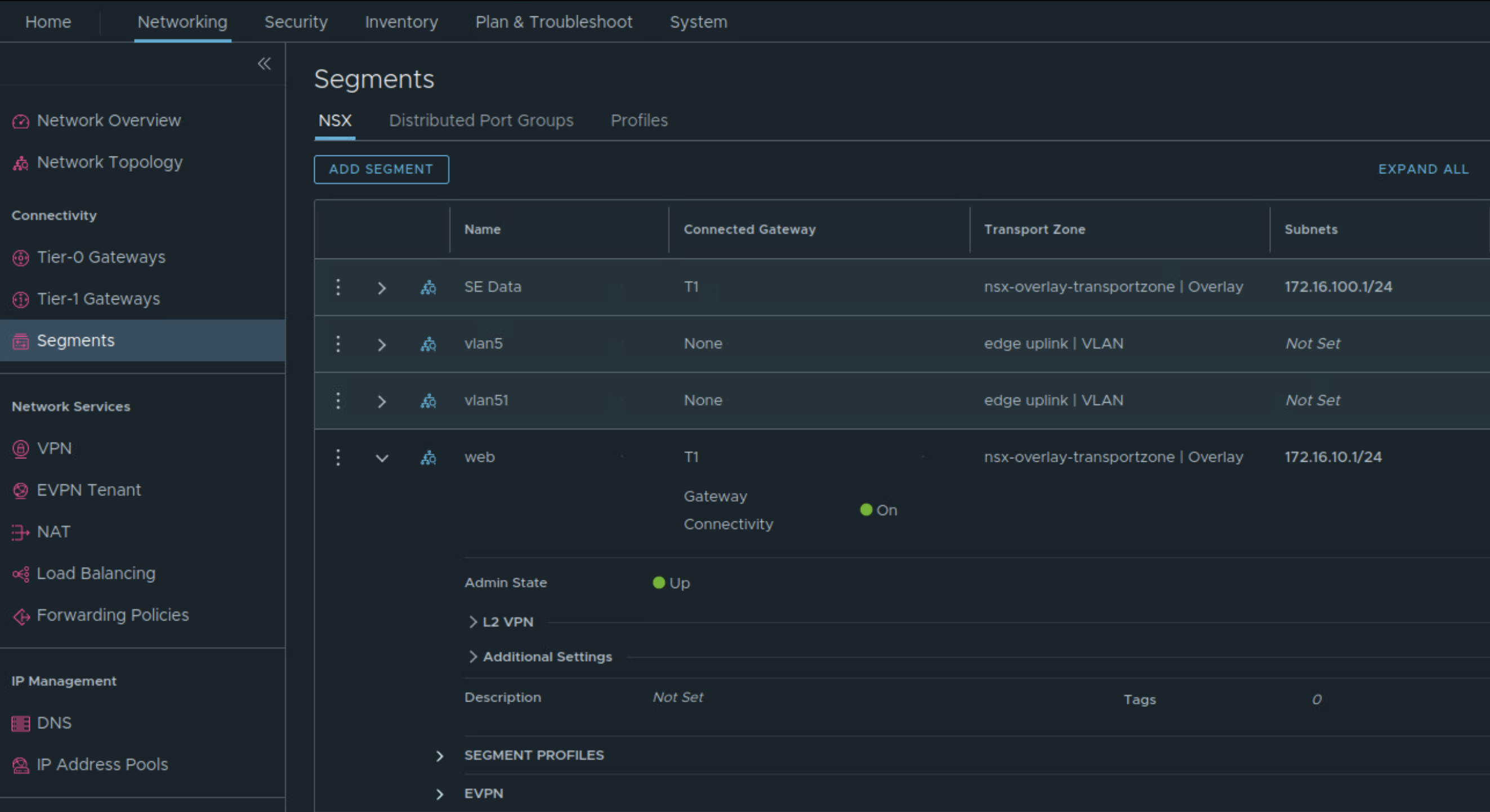
These overlay segments are created and connected to Tier 1 Gateway.
- SE Data: To this network, service engine data interface will be connected.
- Web: To this network, web VMs will be connected.
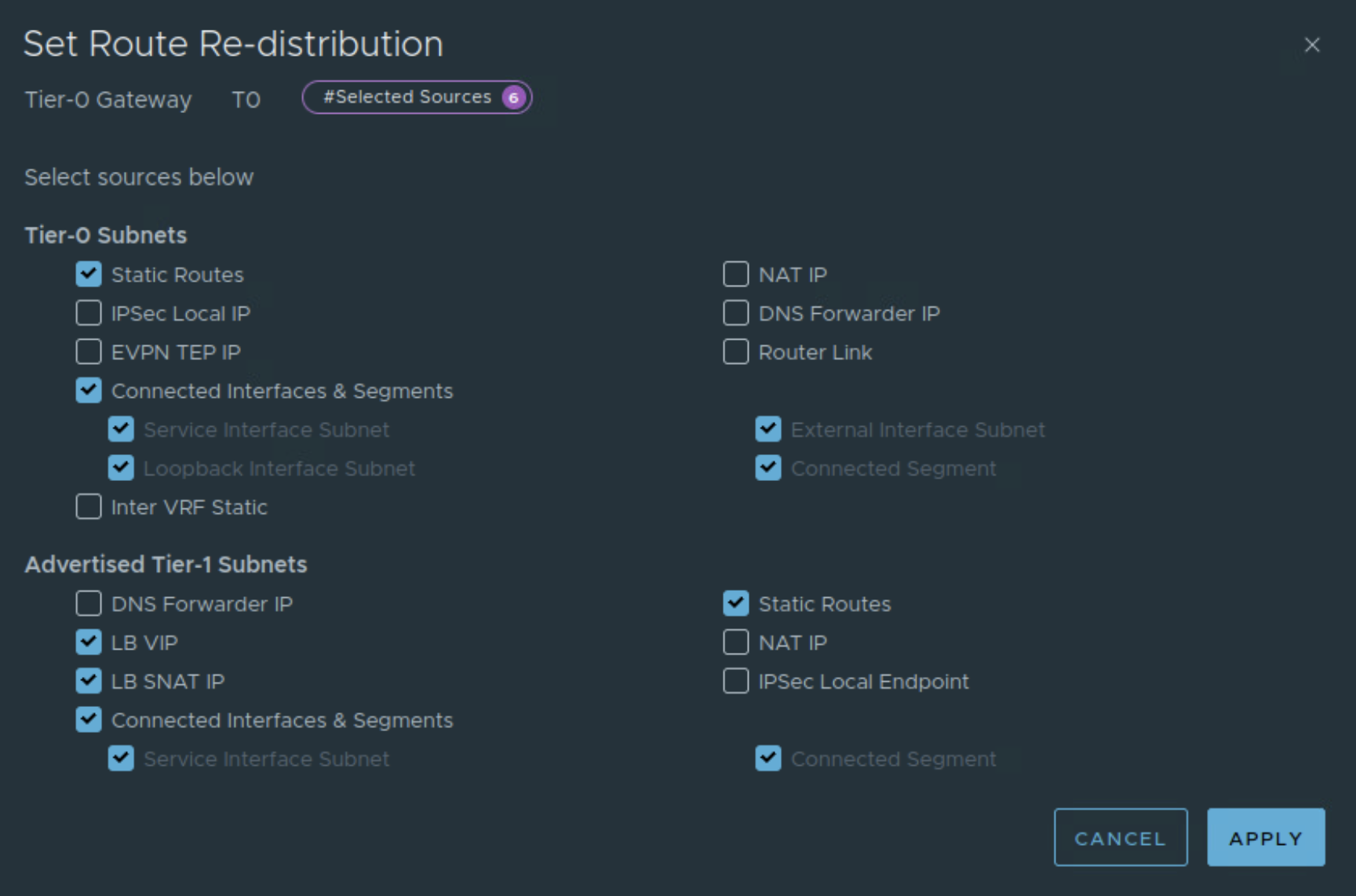
Connect Tier 1 Gateway to upstream Tier 0 Gateway and advertise NSX routes

Also enable route redistribution on Tier 0 Gateway.
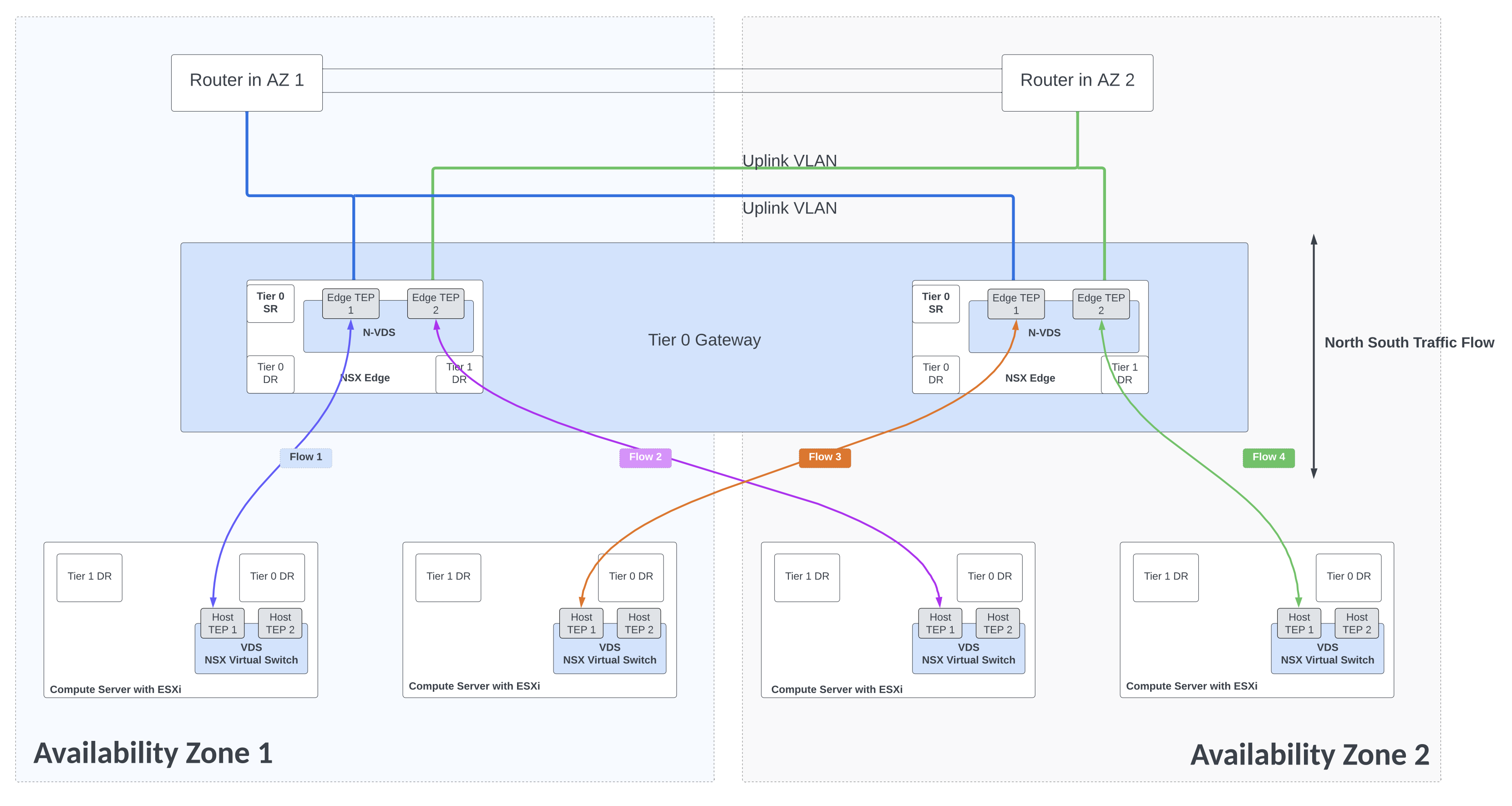
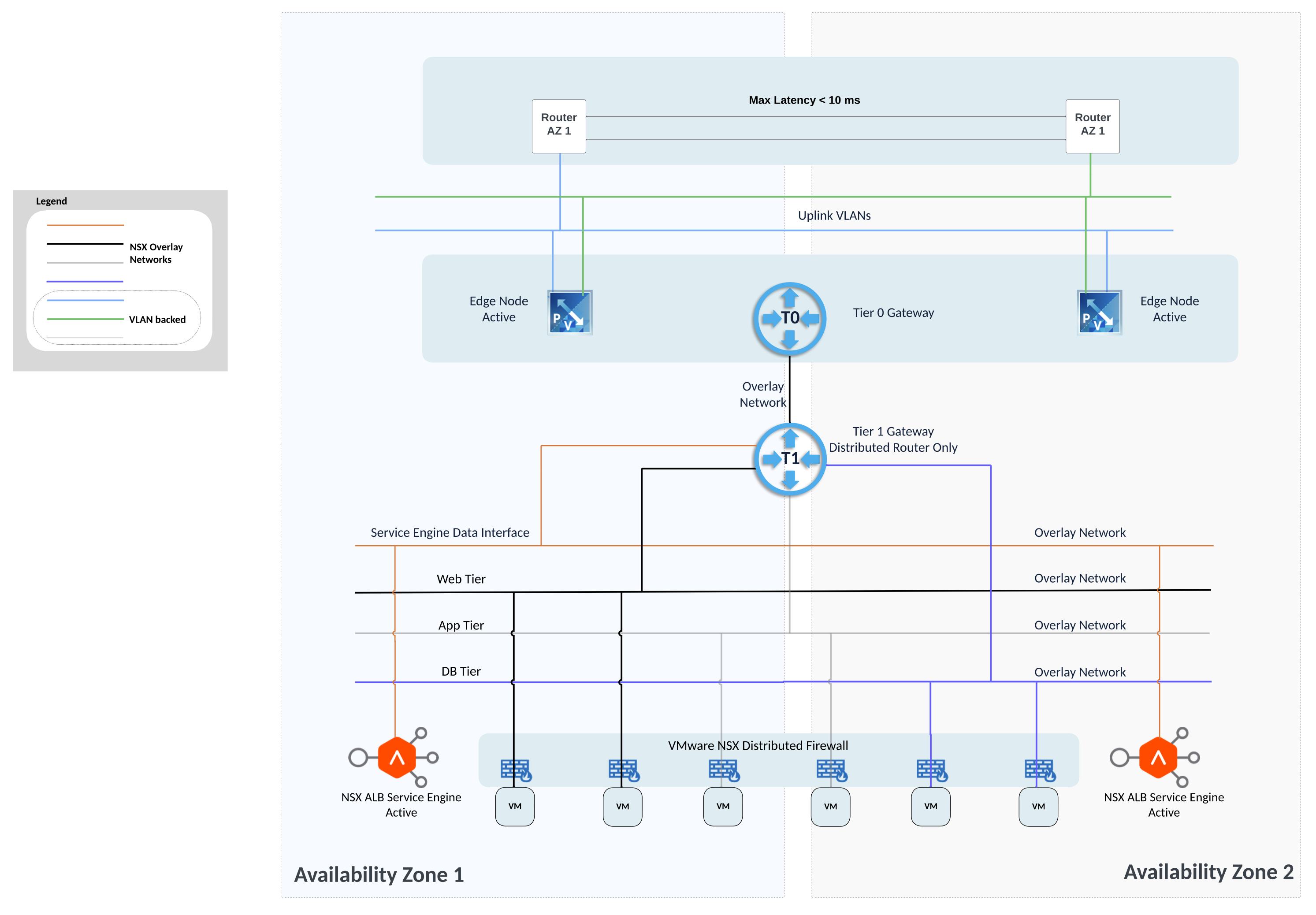
North south traffic flows
NSX Advanced Load Balancer
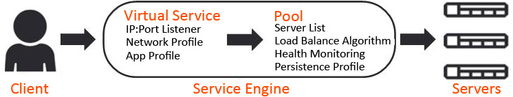
NSX Advanced Load Balancer ALB Architecture:

- Controller: NSX ALB control plane comprises of three controller nodes. The controller is used for management purpose. Controller places virtual service on the data plane component referred to as service engine. Controller nodes communicate with each other and with service engines. Clients access virtual service over required port as shown in the diagram below. Controller to controller latency should be under 10 ms. The health of servers, client connection statistics, and client-request logs collected by the service engines are regularly offloaded to the Controllers.
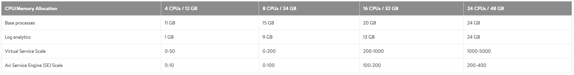
Resources allocated to controller VMs affect the number of virtual services and service engines that can be used. Check the table above.
More than one NSX ALB controller cluster will be needed in case number of service engines exceed 400 or number of virtual services exceed 5000.
- Service Engine SE: is responsible for handling data traffic. Service engine provides data plane functions such as server load balancing, WAF, GSLB. A maximum of nine interfaces of this VM are available for data traffic with the first interface used for management purpose. Service engines are grouped in service engine groups and a particular virtual service can be placed on corresponding service engine group. Multiple service engine groups can be created on ALB controller to serve different environments, line of business. Number of vCPUs allocated to a deployed service engine will eventually consume NSX ALB license. Controller to service engine latency should be under 75 ms. High availability mode for the service engines is configured under SE group settings. Service engine resource allocation vCPU and memory has direct relationship with ALB performance. Several important parameters go into SE group settings:
- vCPU, memory and disk per service engine
- High Availability mode
- Virtual services per service engine
- Max number of service engines
‘Write access’ mode of NSX Advanced Load Balancer ALB offers capabilities like auto creation of service engine when virtual service is created for the 1st time. Networking for the service engine VM is automatically done by the controller. ‘Write access’ mode’ is the recommended deployment mode.
But NSX Advanced Load Balancer ‘No Orchestrator’ mode can be used in situations where it is not possible to consume NSX ALB in ‘write access’ mode. ‘No orchestrator’ mode can be used to build custom setup such as this use-case where both service engines belonging to the same service engine group are split across two different vcenter servers.
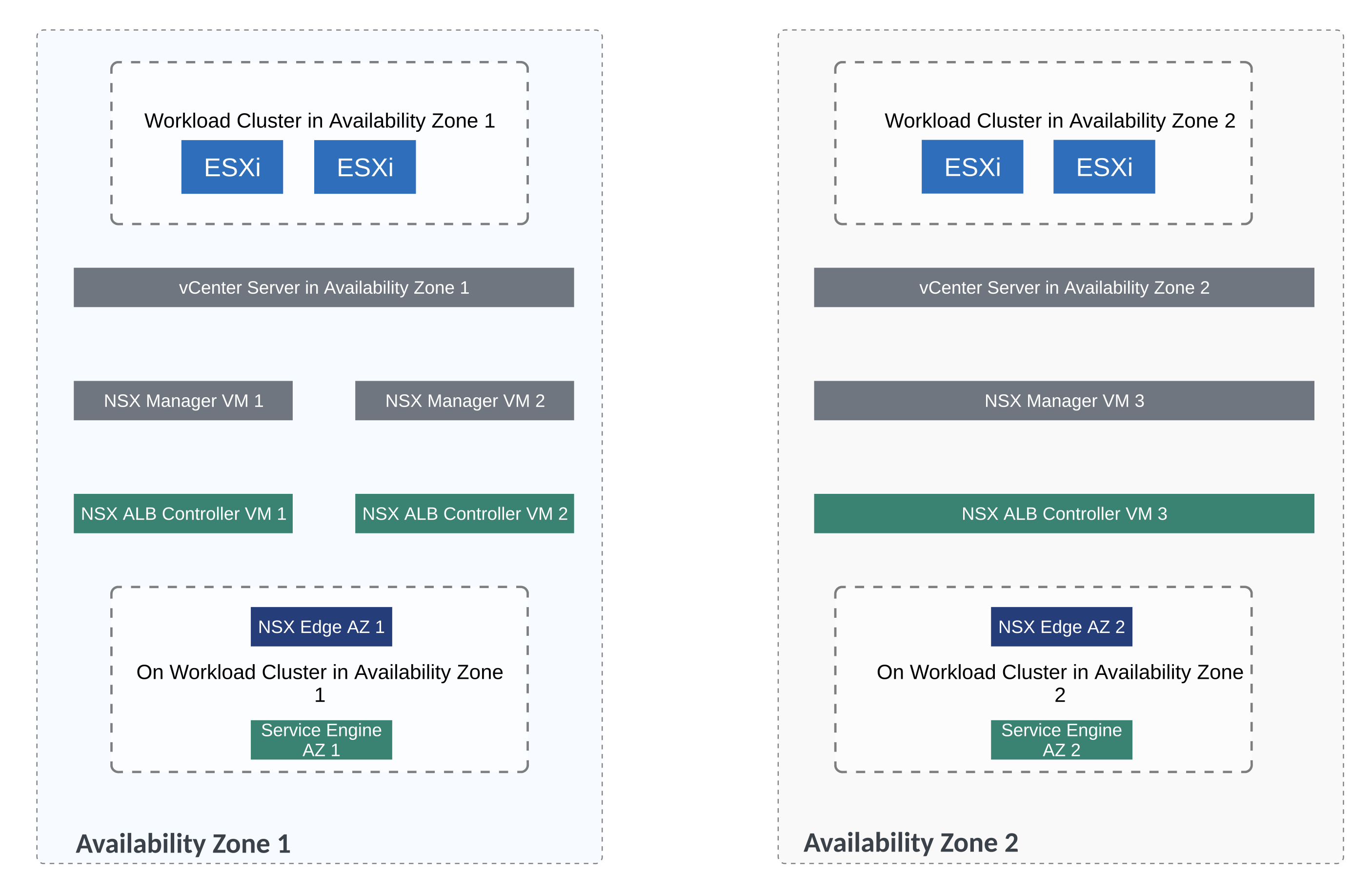
Now for the lab setup, below figures shows the distribution of NSX ALB components
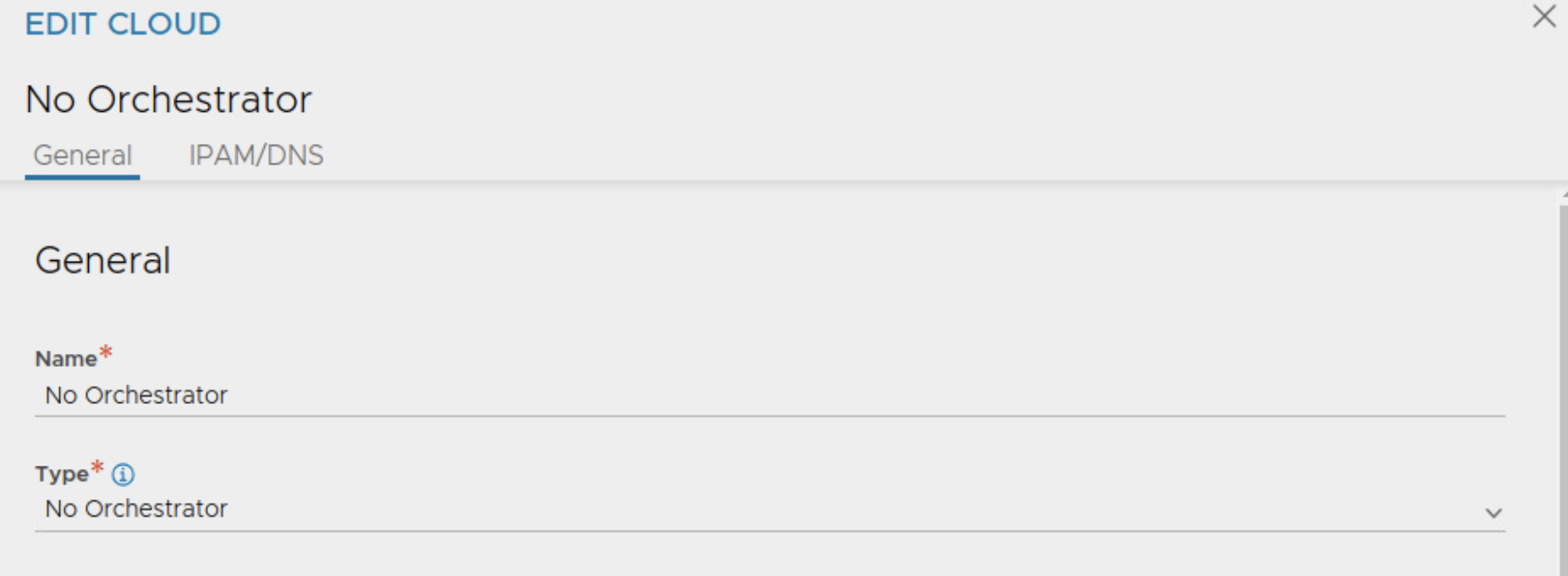
For this lab setup, we will now go through the steps related to NSX ALB configuration in ‘No Orchestrator’ mode.
Create cloud on NSX ALB controller with the type as ‘No Orchestrator’
Next we will deploy OVA for service engine.
1st service engine in this lab will be deployed on workload cluster of AZ1
And 2nd service engine will be deployed on workload cluster of AZ2

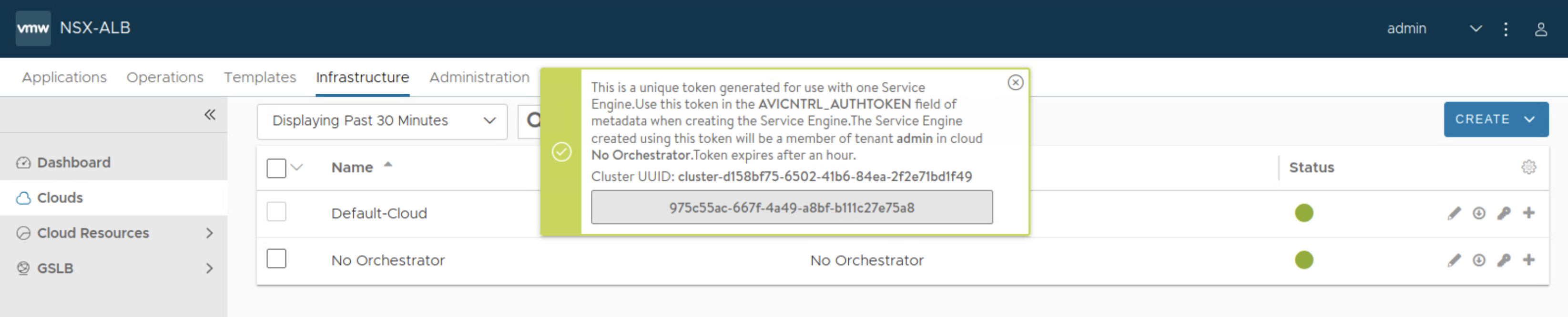
While deploying the OVA for service engine, token will be needed. You can fetch this from NSX ALB UI as shown below, make sure token is for the cloud type ‘No Orchestrator’
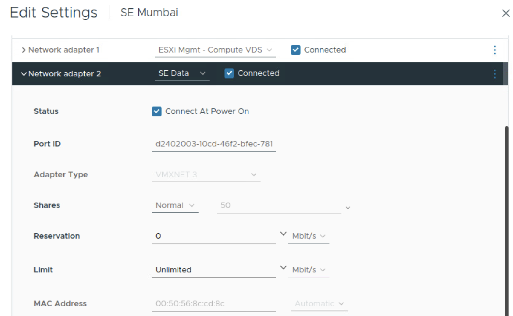
While deploying the OVA for service engine, ensure correct networks/port groups are selected for management interface and data interface of the service engine. Those need to be pre-existing before deploying OVA for service engine.
Once the service engine is powered on, it will connect to NSX ALB controller and it will appear in NSX ALB UI

Fetch the mac address of data interface vnic on the service engine from vSphere client. This will be useful while configuring IP addressing on service engine data interface. Notice below that the mac address ends with cd8c
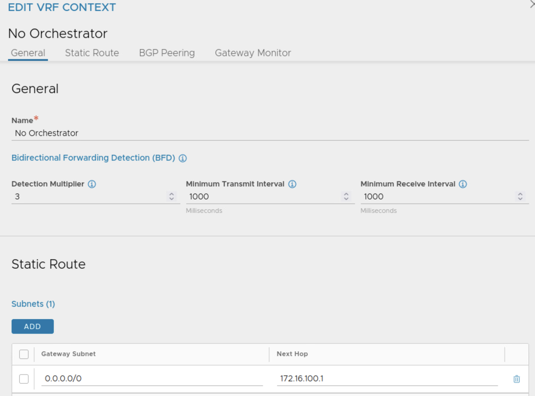
I will configure VRF for the service engine data interface and configure default gateway in this VRF
Next I will configure IP address on data interface of service engine based on the MAC address of the interface and I will ensure that the interface belongs to the newly created VRF.

Repeat these steps for deploying service engine on workload cluster of AZ 2:
- Deploy service engine using OVA.
- Configure IP address on data interface of service engine by comparing MAC address shown in vSphere client interface.
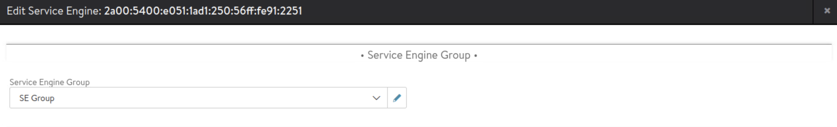
Next I will create service engine group and ensure newly deployed service engines belong to this service engine group.


Here, I am using these settings on service engine group:
- Cloud is ‘No Orchestrator’
- Active Active HA group
- 100 Virtual Services per service engine
- Each virtual service will be scaled to at least 2 service engines
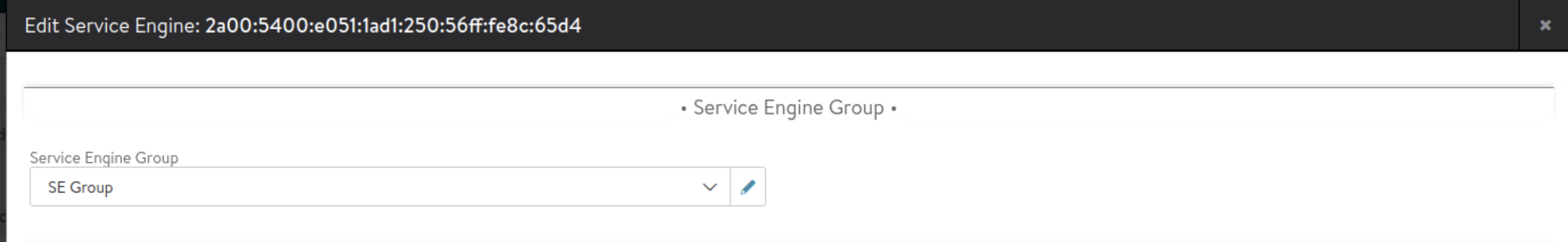
Select each service engine and assign to this service engine group.
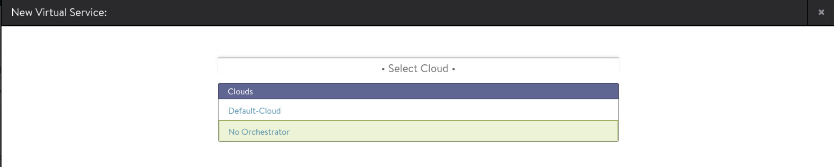
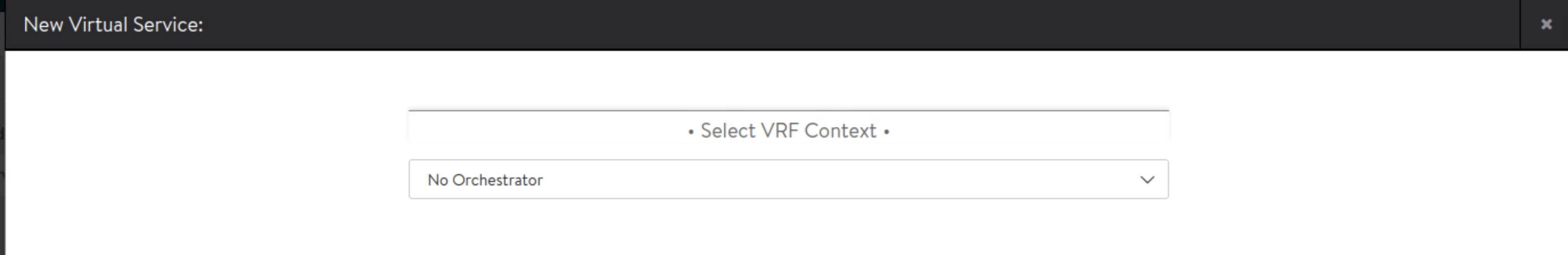
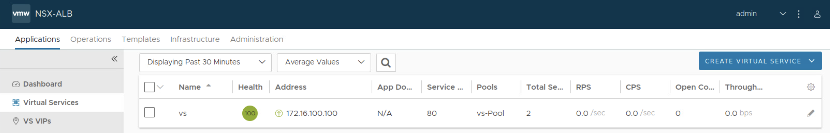
Next create virtual service under ‘No Orchestrator’ cloud.

And that concludes this post.
Hope you find it useful!
