

We have covered cross vcenter NSX with OSPF previously.
Here we cover cross vcenter NSX with BGP.
In this above topology:
- There are two vcenters, one in the primary site and the other in DR site.
- Primary NSX manager is deployed in primary site.
- Secondary NSX manager is deployed in DR site.
- Primary NSX manager is linked with vcenter in primary site.
- Secondary NSX manager is linked with vcenter in DR site.
- Universal controller cluster is deployed under vcenter 1 in primary site.
- Cross vcenter NSX is configured using the primary and secondary NSX managers.
- Universal transport zone is defined which will span the clusters across both sites. We are able to define universal logical switches using this single universal transport zone. Keep in mind that we are able to deploy only one universal transport zone. As a rule, we cannot deploy more than one Universal Transport Zone. And all universal objects are only defined from primary NSX manager.
- Two NSX edges are deployed in primary site and two NSX edges are deployed in DR site.
- This is a active/passive model and we will ensure ingress/egress traffic goes via the primary site. This is a preferred setup since it gives deterministic traffic flow and keeps the traffic flow symmetrical, ingress/egress via a particular site.
- To influence inbound traffic, we will leverage BGP AS Path Prepending in the physical network.
BGP Configuration:
As depicted in topology above:
- iBGP is used within NSX domain. UDLR has four iBGP peerings with the NSX edges of both sites.
- Single private AS 64512 is used within NSX domain
- BGP AS 1 is used in the physical network upstream.
- eBGP is used between NSX edges and the physical routers
- iBGP is used between UDLR and NSX edges.
- We will modify BGP weight on UDLR to influence outbound traffic.
- NSX domain is like a stub network. Hence there is no hard requirement of full mesh iBGP within this NSX domain.
- We are going to redistribute connected networks on UDLRs and the edges.
- Default route will be sent by the physical routers towards NSX edges only through the eBGP peering. This configuration is covered in the BGP configurations below.
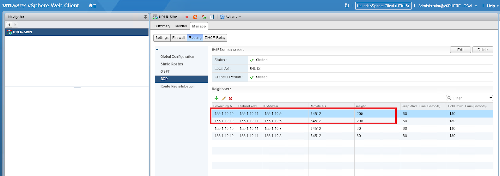 BGP Weight Modification on UDLR
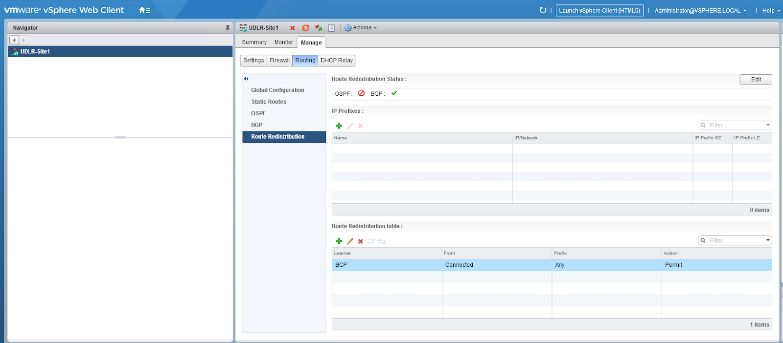 Redistribute connected on UDLR
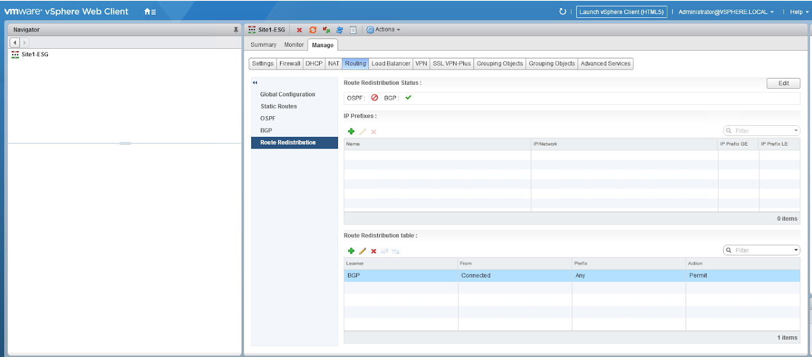 Redistribute connected on the NSX Edge
 iBGP peerings on UDLR
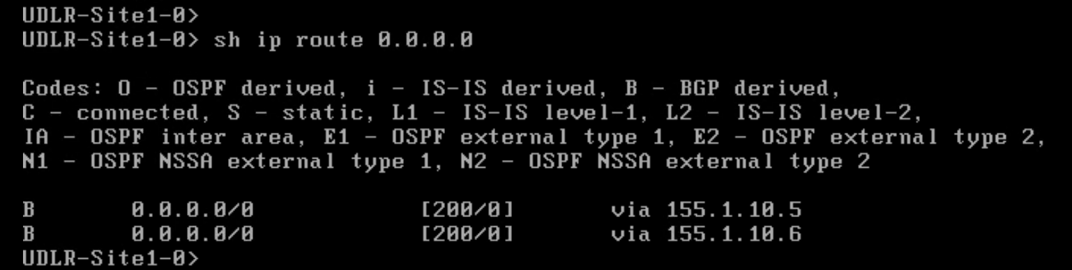 Default route on UDLR
Now let’s also map this topology with Cisco routers and lab this up.
I’ve added UDLR2 as well in this topology.
Ingress/egress traffic for subnets behind UDLR2 will be via DR site. This is covered in the traffic flow section.
BGP setup for Cross Vcenter NSX using Cisco routers
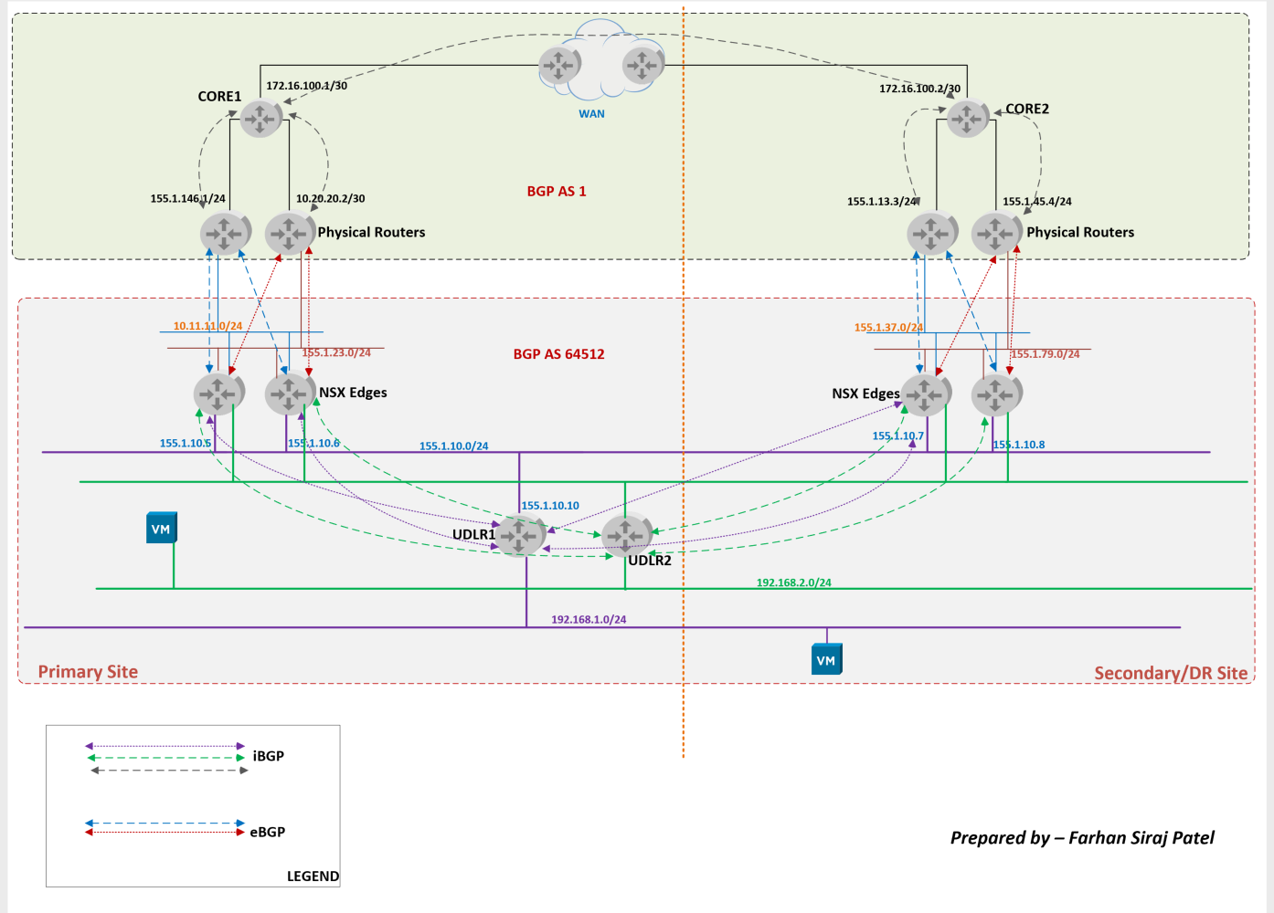
This topology above is for demo purpose only.
Core 1 and Core 2 routers in topology above are single point of failures. Also the route reflector configuration in this topology has single point of failures. Ideally redundant route reflectors should be deployed for exchange of route updates.
Appropriate measures should be taken while designing production networks to avoid such single point of failures.
- This topology is essentially utilized to cover the BGP configs relevant to NSX.
- The appropriate BGP peerings are depicted in the diagram above.
- Core 1 is configured as route-reflector for physical routers in primary site.
- Core 2 is configured as route-reflector for physical routers in DR site.
- Core 1 and Core 2 have i BGP peering between them.
- OSPF is utilized as IGP in BGP AS 1
- Physical routers are sending a default route towards NSX edges only.
- AS Path Prepending has been configured on physical routers of DR site for subnets behind UDLR1. This will ensure ingress/egress traffic for subnets behind UDLR1 is via primary site.
- For subnets behind UDLR2, AS Path prepending will be done for these subnets in primary site. Ingress/egress traffic flow towards subnets behind UDLR2 will be via DR site.
Important notes about updates in a route-reflector setup:
- Update received from a route-reflector client will be send across to other clients, non-clients and eBGP peers
- Update received from a non client will be send across to other clients and eBGP peers only and such update will not be sent to other non clients. In the topology above, Core 2 is a non client for Core 1. Also Core 1 is a non client for Core 2.
- Update received from a e BGP peer will be sent across to clients, non clients and other e BGP peers.
Router Configurations
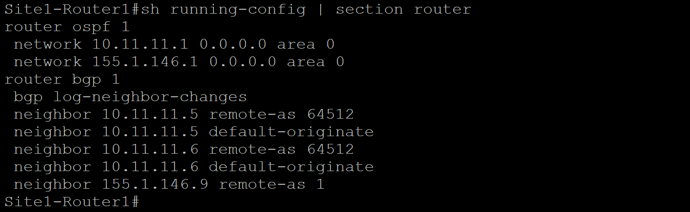 Site 1 Router 1 Config
 Site 1 Router 2 Config
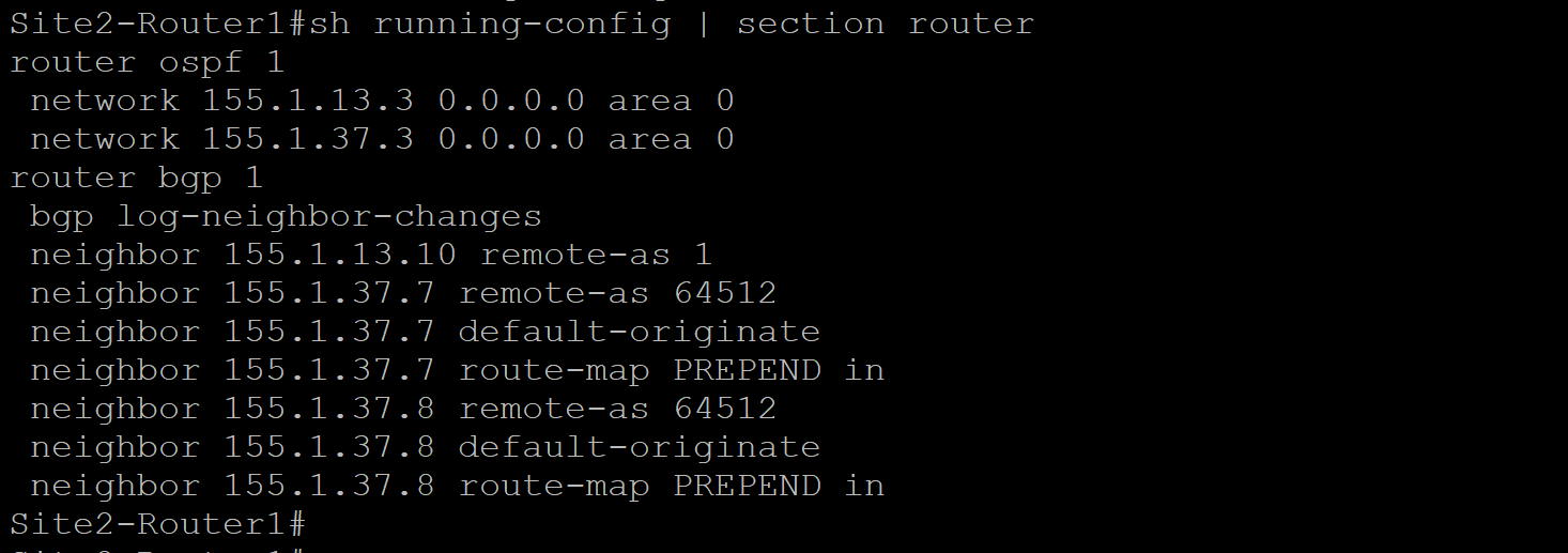 Site 2 Router 1 Configuration
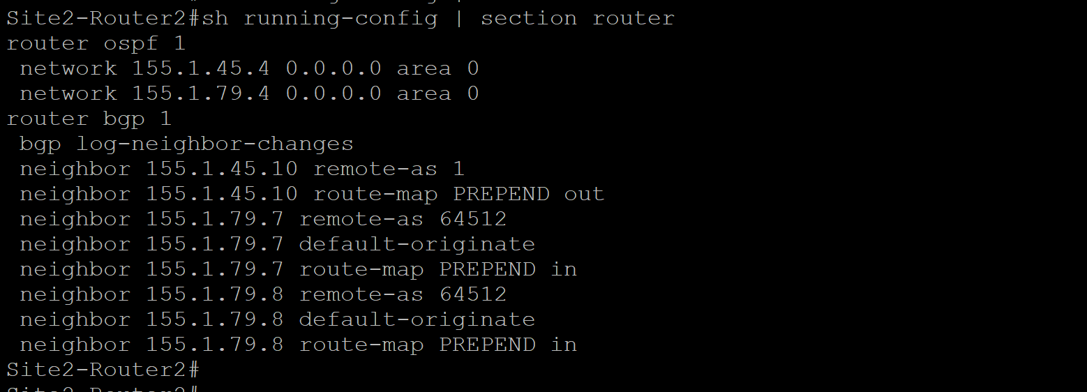 Site 2 Router 2 Configuration
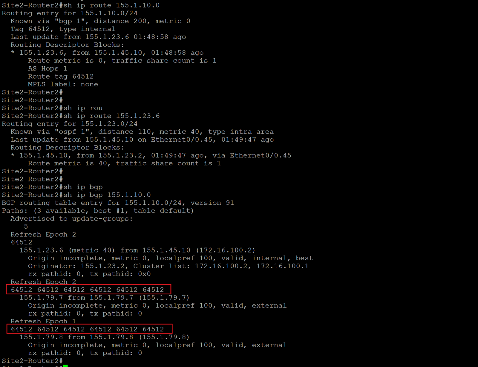 Route lookup for 155.1.10.0/24 on Site 2 Router 2
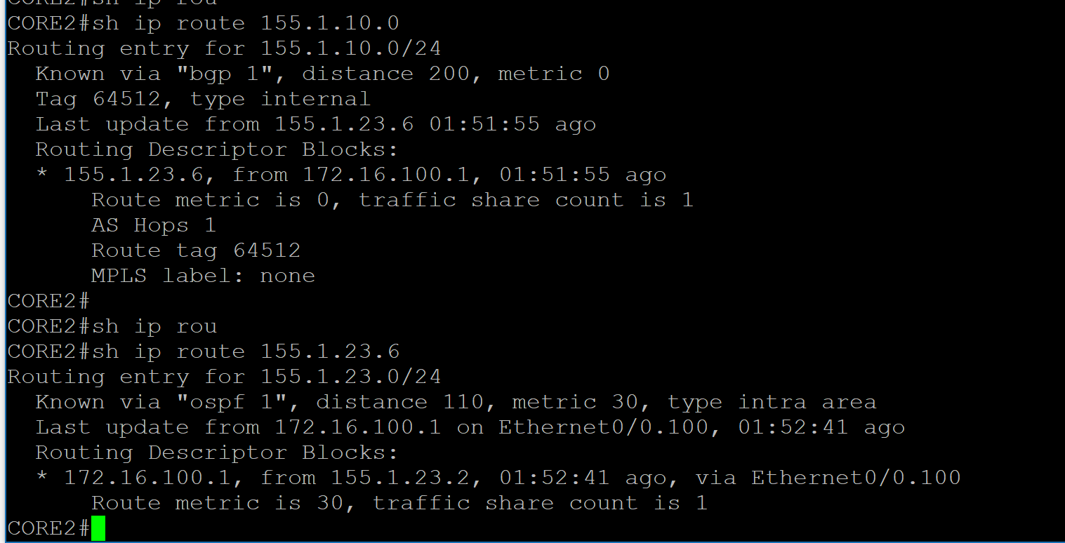 Route lookup for 155.1.10.0/24 on Core 2
Notice only the best path is sent from Site2-Router2 towards Core2
Traffic Flows
 Traffic flow towards subnets behind UDLR1
 Traffic flow towards subnets behind UDLR2
Hi Farhan, I assume there is a typo in your first Cisco topology diagram. UDLR1 should be peering with both edges at the secondary site? Currently both purple arrows are pointing to 155.1.10.7.
Thanks for a great post!
LikeLike