
NSX-T Routing Configuration
 |
| Overall Topology used in the lab |
Pre-requisites like NSX-T manager installation, preparing and configuring compute host transport nodes, preparing and configuring edge transport nodes are covered here.
As shown in the topology above, two Tier 0 gateways are configured in the lab.
One Tier 0 gateway is configured in Active-Active High Availability mode and the other Tier 0 gateway is configured in Active-Passive High Availability mode.
I will be referring to the two Tier 0 Gateways as Tier 0 Gateway Left and Tier 0 Gateway Right.
A total of four edge node VMs are utilized, two for each Tier 0 gateway.
Edge node clusters are created, two edge node clusters are defined. Each edge node cluster effectively utilizes two edge node VMs.
 |
| BGP peerings |
The above topology shows the e BGP peerings between NSX-T Edge Nodes and the physical routers.
Two VLANs are utilized as shown above.
 |
| Edge Transport Nodes
Here you see that Edge Transport Nodes are ready.
Below you find the interface configs applied on the Tier 0 Gateways.
|
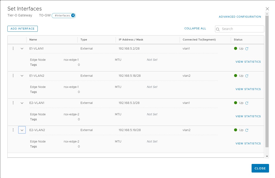 |
| Interfaces belonging to Edge Nodes on Tier 0 Gateway Left |
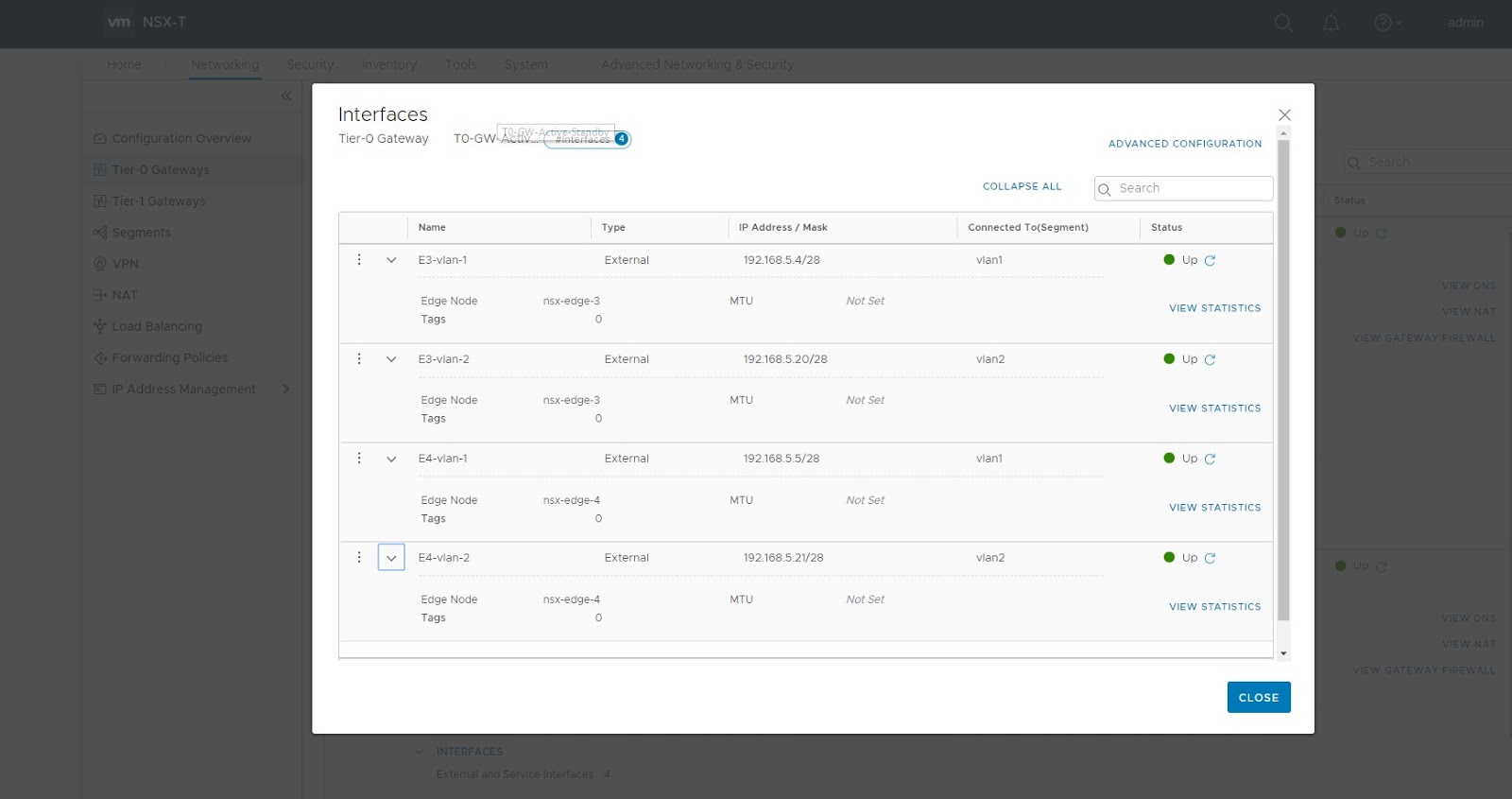 |
| Interfaces belonging to Tier 0 Gateway Right |
 |
| BGP Diagram along with IP addressing |
This topology shows the BGP AS numbers used in the lab setup.
Also shown in the diagram is the IP addressing used.
Segment with subnet 172.16.10.0/24 is attached to a Tier 1 Gateway Left.
And a segment with subnet 10.0.0.0/24 is directly attached to Tier 0 Gateway Right.
========================================
BGP Configuration on Tier 0 Gateway
 |
| Add caption |
For BGP configuration, edit the Tier 0 Gateway and configure first the Local BGP AS number and save the configuration.
Next set the BGP peers.
 |
| BGP peer configuration on Tier 0 Gateway |
You will apply similar BGP configuration on the other Tier 0 Gateway Right but in that case the Local BGP AS number is 65002 as shown in the BGP topology above and the remote AS number will be same i.e. 65001
BGP configuration on the TOR Physical Routers
Make sure you have BGP configured on the physical routers and also ensure that the BGP peerings are up.
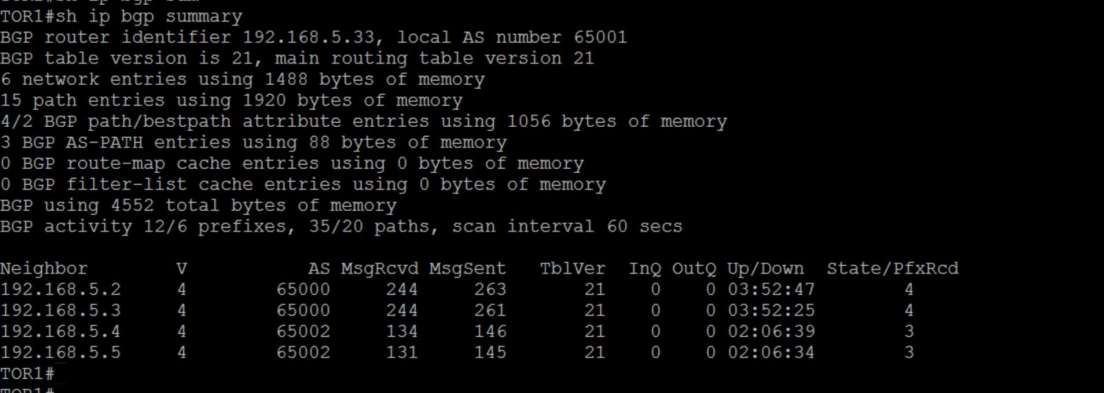 |
| BGP peerings on TOR1 |
 |
| BGP Peerings on TOR2 |
============================================
Configure redistribution on Tier 0 Gateways and Tier 1 Gateway
As mentioned in my earlier post, there is no dynamic routing between Tier 0 gateway and Tier 1 gateway in NSX-T.
We just need to configure redistribution on Tier 0 Gateway and Tier 1 Gateway appropriately.

As shown above, we are redistributing connected networks on Tier 1 Gateway
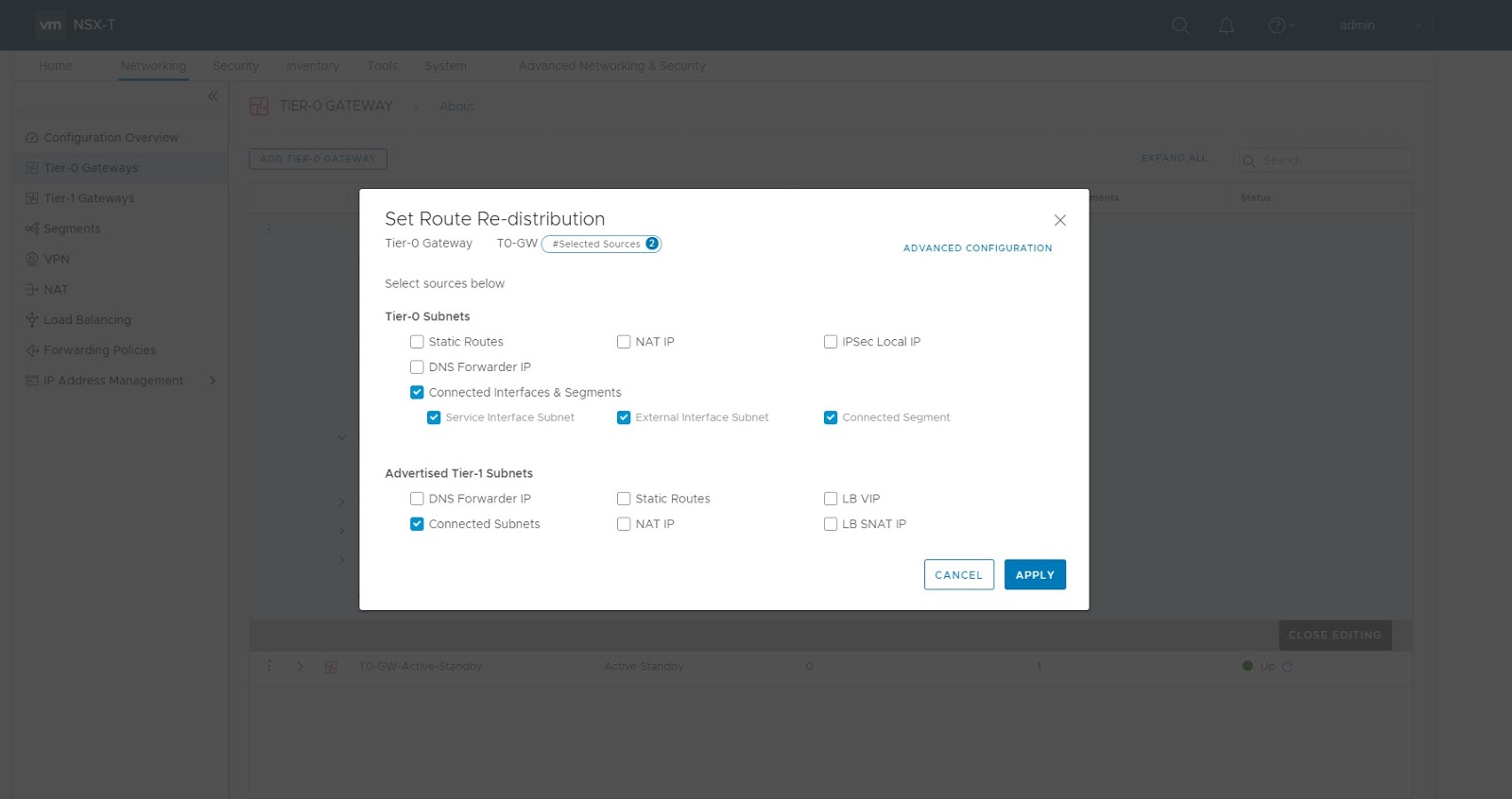
Enable redistribution on Tier 0 Gateway.
Ensure you also redistribute connected subnet of Tier 1 gateway on Tier 0 gateway.

Follow the same steps to enable redistribution of connected subnet on Tier 0 Gateway Right.
===============================================
Validation


 |
| High Availability Mode on Tier 0 SR |
Check the high availability status of this Tier 0 SR corresponding to Tier 0 Gateway Left and you will find that it is Active-Active
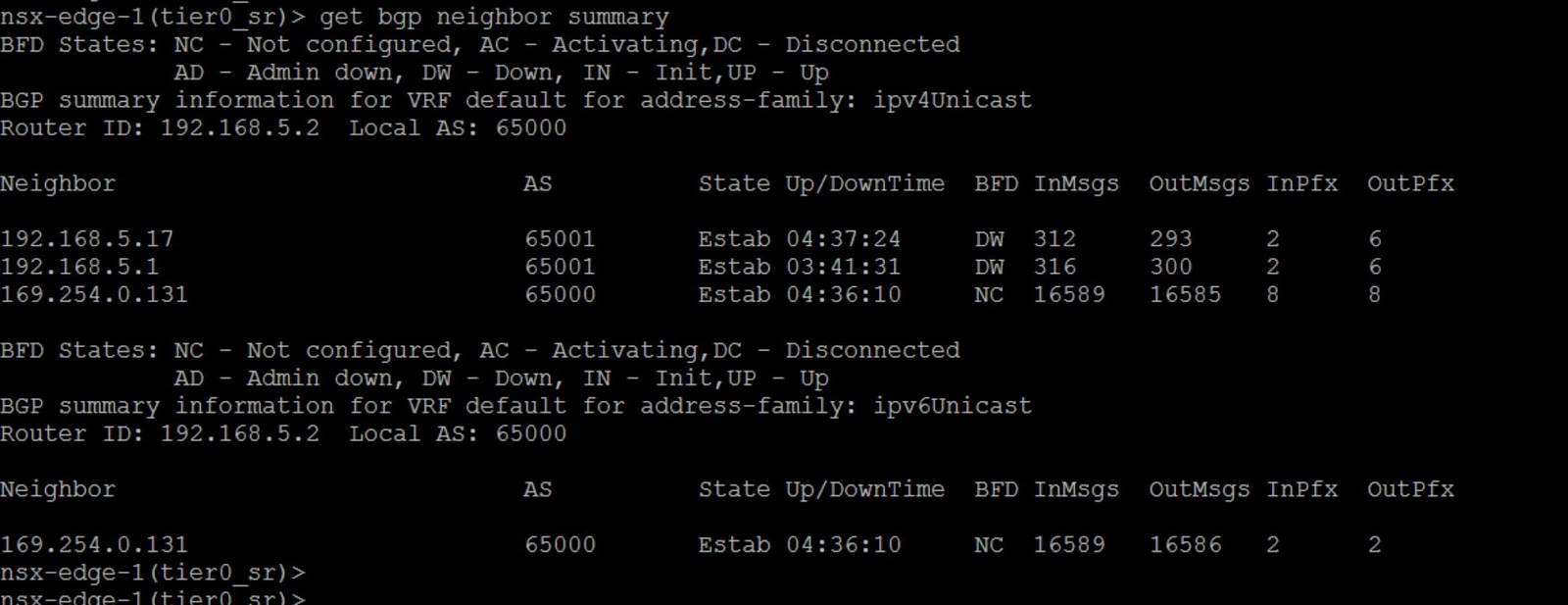 |
| BGP Peerings on Tier 0 SR corresponding to Tier 0 Gateway Left |


=======================================
Validation on the physical routers for subnet connected to Tier 0 Gateway Right
Let’s check how the route for 10.0.0.0/24 (which is locally connected to Tier 0 Gateway Right) is learnt by physical routers


Notice from the output above, that the route is learnt via the Active Edge Node VM corresponding to Tier 0 Gateway Right.
Standby Edge Node VM corresponding to Tier 0 Gateway Right is doing Auto AS Path Prepend.
There is no explicit configuration done on the Tier 0 Gateway to achieve this AS path prepend.
=========================
End to end connectivity between Windows VM attached to 10.0.0.0/24 and Ubuntu machine connected to 172.16.10.0/24
Use ping and trace to verify connectivity between source and destination VM.
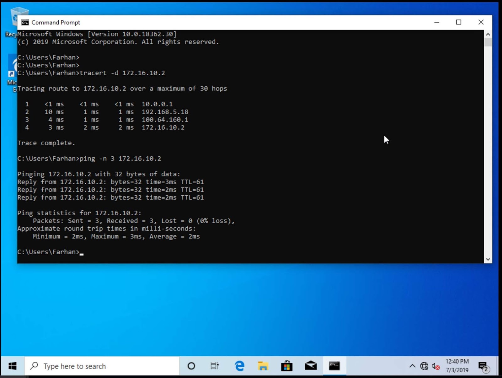

Ensure that you are able to ping with default VM MTU of 1500 bytes.
