
NSX Advanced Load Balancer ALB Architecture:

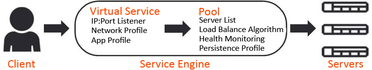
- Controller: NSX ALB control plane comprises of three controller nodes. The controller is used for management purpose. Controller places virtual service on the data plane component referred to as service engine. Controller nodes communicate with each other and with service engines. Clients access virtual service over required port as shown in the diagram below. Controller to controller latency should be under 10 ms. The health of servers, client connection statistics, and client-request logs collected by the service engines are regularly offloaded to the Controllers.
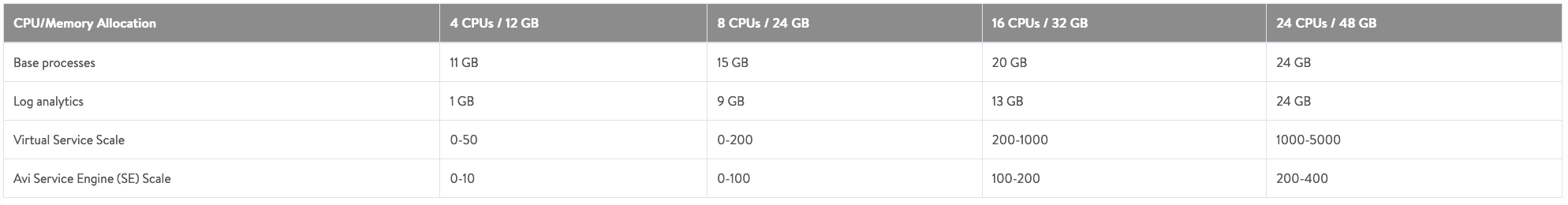
Resources allocated to controller VMs affect the number of virtual services and service engines that can be used. Check the table above.
More than one NSX ALB controller cluster will be needed in case number of service engines exceed 400 or number of virtual services exceed 5000.
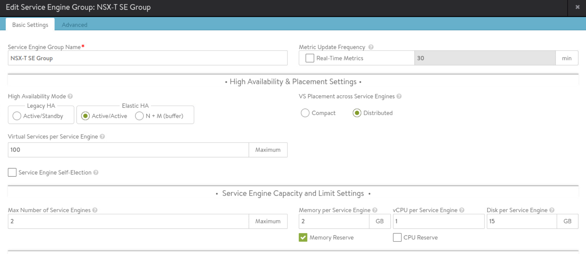
- Service Engine SE: is responsible for handling data traffic. Service engine provides data plane functions such as server load balancing, WAF, GSLB. A maximum of nine interfaces of this VM are available for data traffic with the first interface used for management purpose. Service engines are grouped in service engine groups and a particular virtual service can be placed on corresponding service engine group. Multiple service engine groups can be created on ALB controller to serve different environments, line of business. Number of vCPUs allocated to a deployed service engine will eventually consume NSX ALB license. Controller to service engine latency should be under 75 ms. High availability mode for the service engines is configured under SE group settings. Service engine resource allocation vCPU and memory has direct relationship with ALB performance. Several important parameters go into SE group settings:
- vCPU, memory and disk per service engine
- High Availability mode
- Virtual services per service engine
- Max number of service engines
In this blog, we will create NSX-T VLAN based cloud on NSX ALB controller.
Bear in mind that you can also create NSX-T cloud backed by overlay networks. NSX-T overlay networking provides key benefits like distributed routing, abstraction from physical network.
One key benefit of creating NSX-T cloud on NSX ALB is that life-cycle management of service engines is handled by ALB Controller; service engines are auto deployed once virtual service is created. Also NSX-T security groups can be used for server pool configuration on NSX ALB. Once NSX-T cloud is created on ALB, controller by itself will upload SE image to content library of vcenter server.
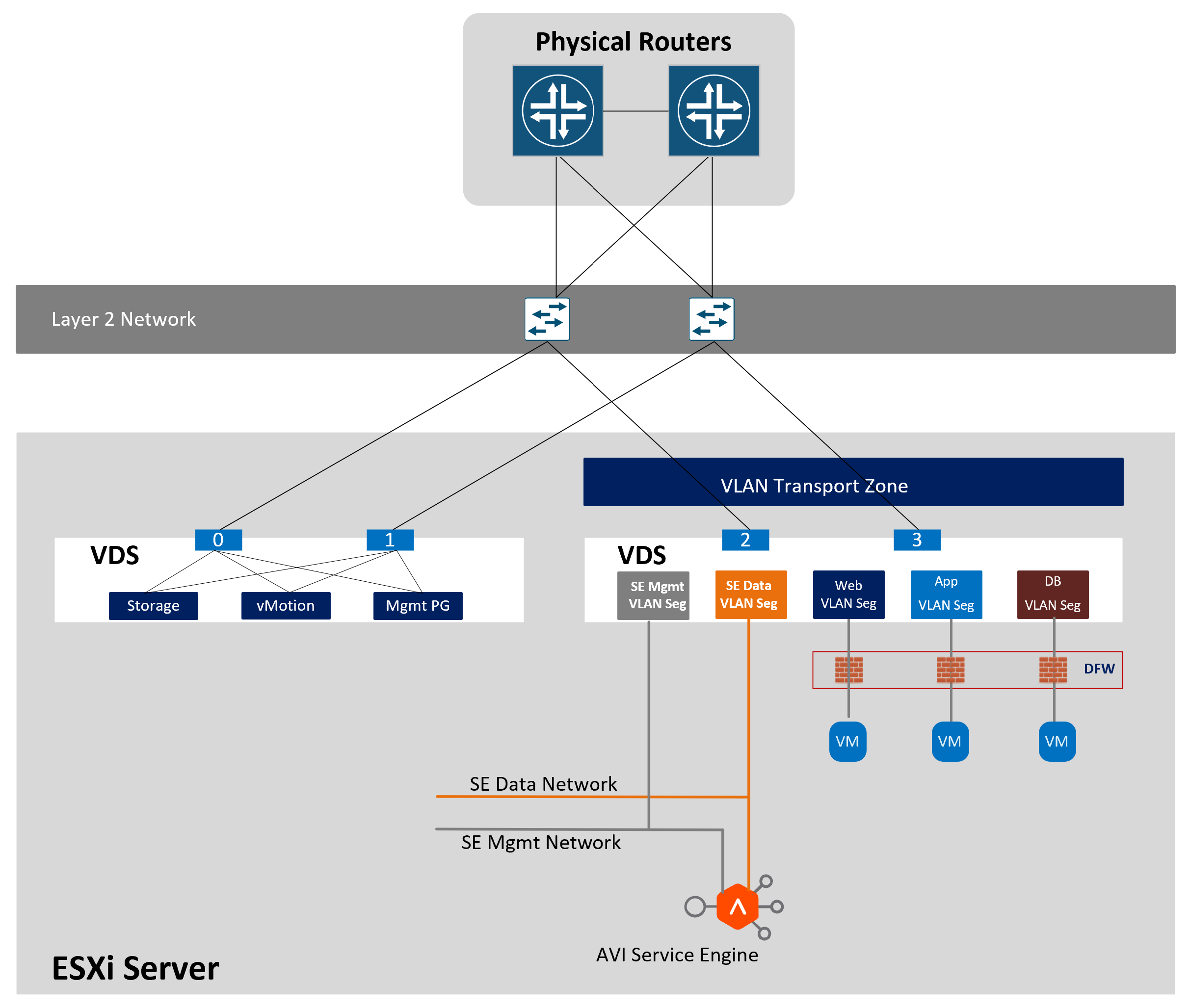
In this lab, I will be using NSX-T VLAN segments. Gateways for the subnets will reside on the physical routers.
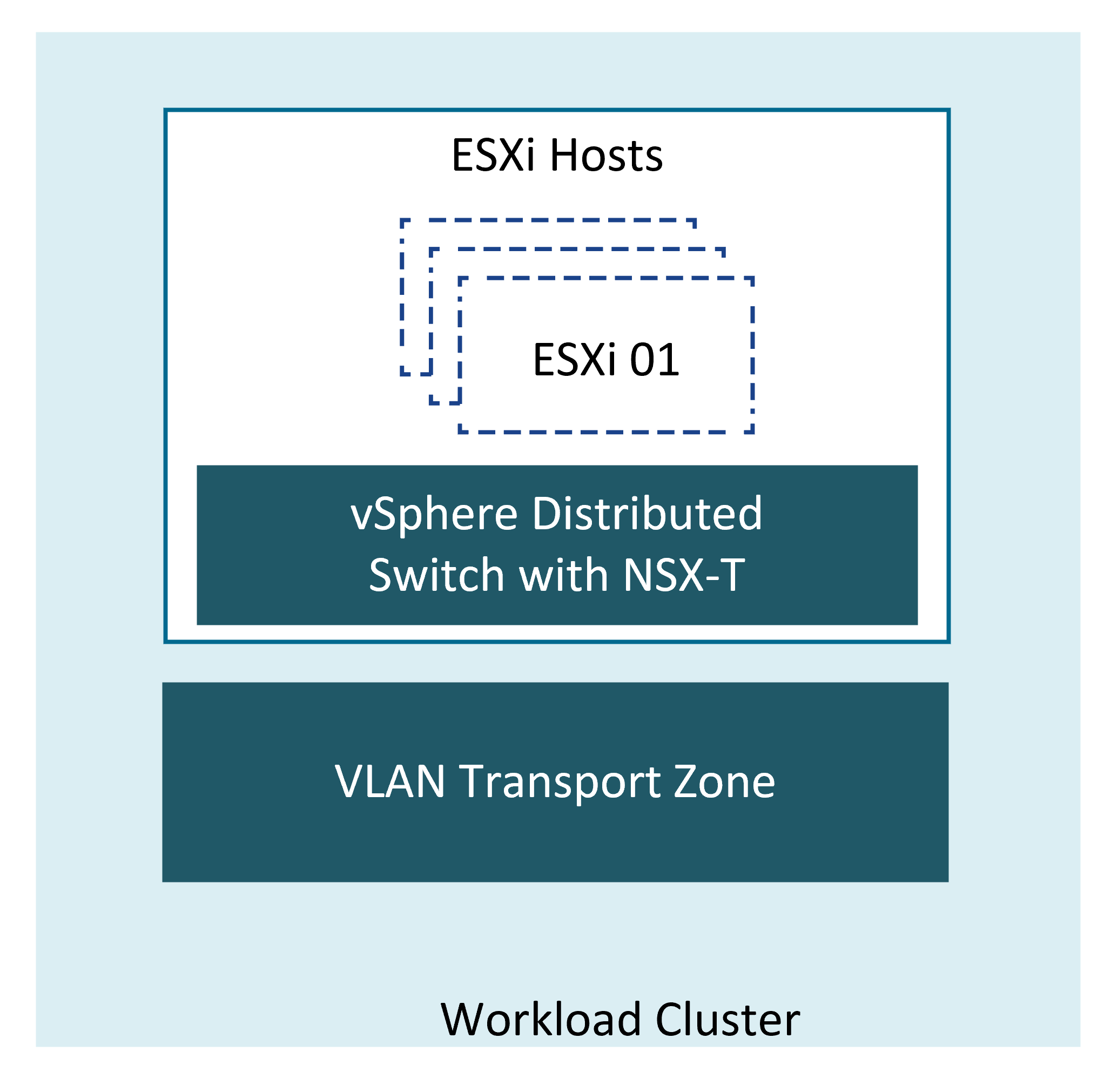
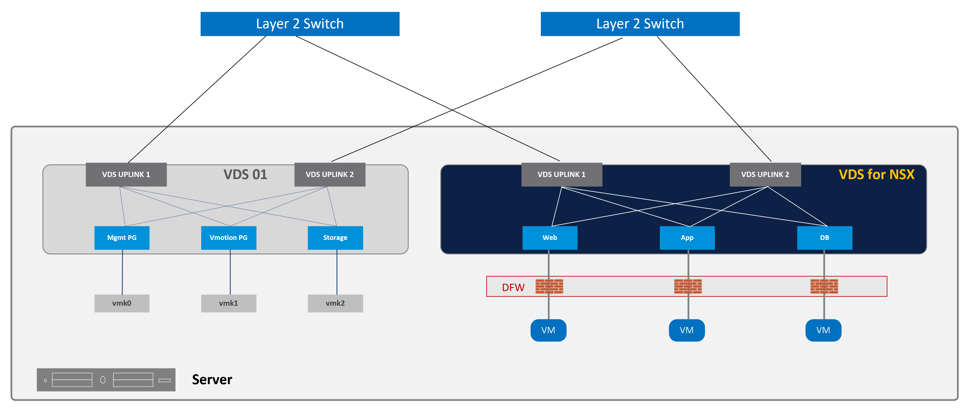
vSphere setup in my lab is as below:

I have deployed single vcenter server and one NSX manager cluster. These components along with NSX ALB controller typically reside on management cluster. Controller OVA is downloaded from the portal and the three VMs are deployed from vcenter server. Controller clustering is then done and cluster IP is allocated from the same subnet as that of controller nodes. Data plane component of NSX ALB (service engine) is deployed on workload cluster as shown above. Creation of NSX-T cloud on NSX ALB Controller allows auto deployment of this data plane component (service engine).
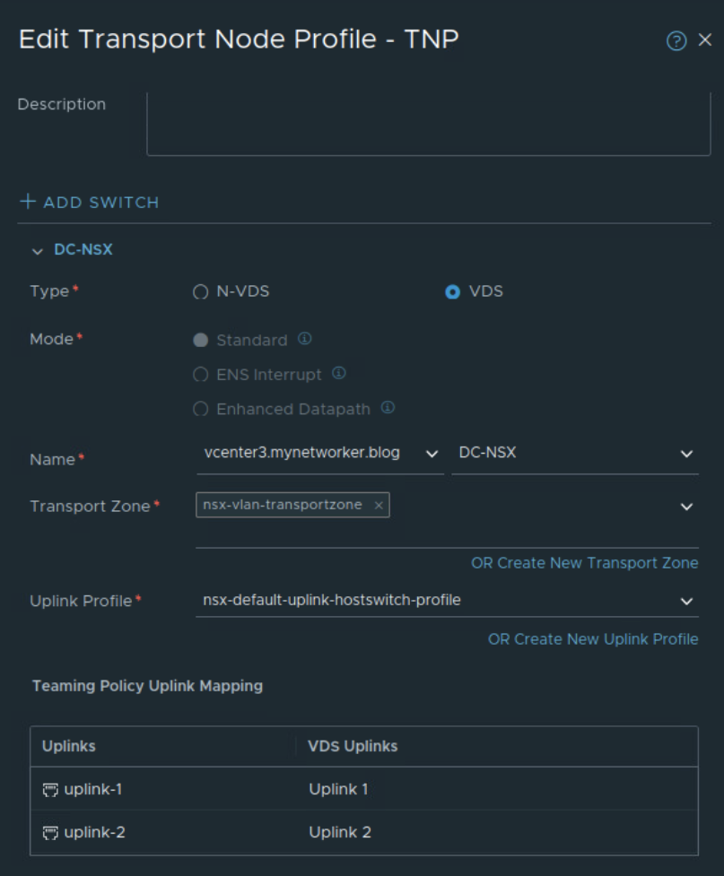
Servers are prepared for NSX using the above transport node profile on NSX manager.

Next I will create required NSX VLAN segments from NSX manager and will configure corresponding L3 interface on the physical routers.

Management interface of NSX ALB service engines will be connected to NSX VLAN Segment with VLAN ID 12
Data interface of NSX ALB service engine will be connected to NSX VLAN Segment with VLAN ID 13
In this example, servers are connected to NSX VLAN segment with VLAN ID 13. But your servers can also reside in another NSX-T VLAN segment for example with VLAN ID 14
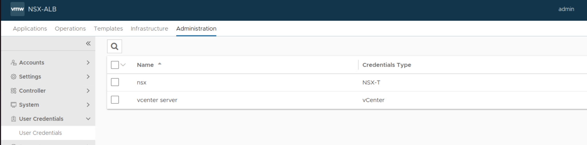
I will create required user credentials on NSX ALB Controller first.
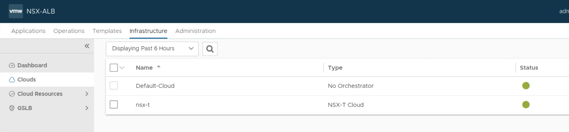
Next I will create NSX-T cloud


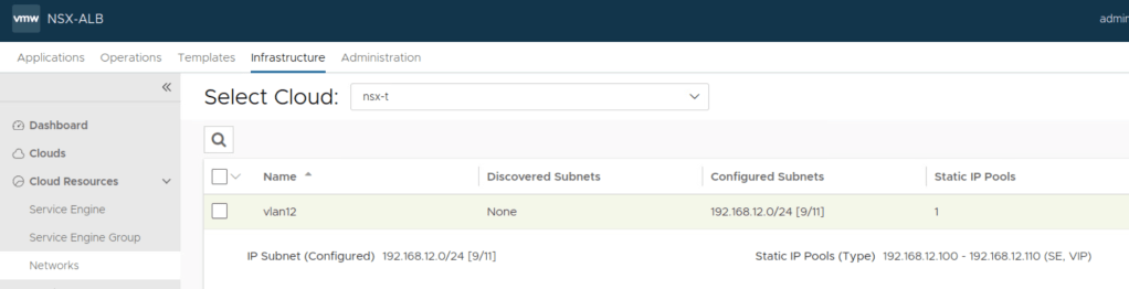
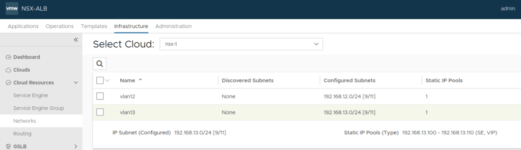
Assign static IP pools on NSX ALB Controller for:
Service Engine management network and
Service Engine data network
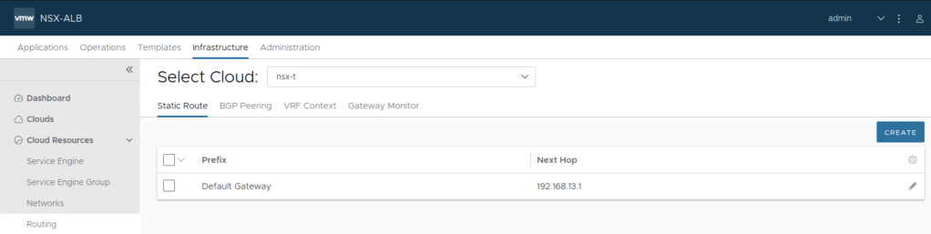
Specify default gateway for data network of service engine under Routing
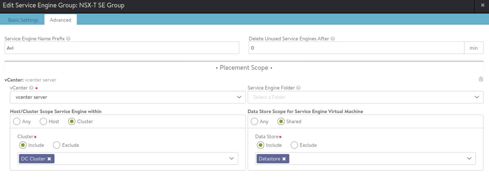
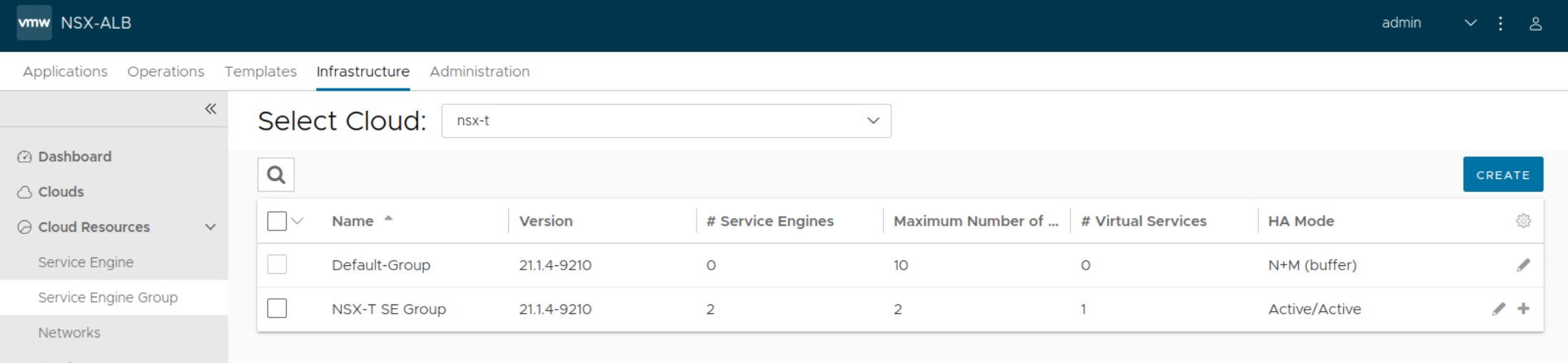
I will create custom service engine SE group.
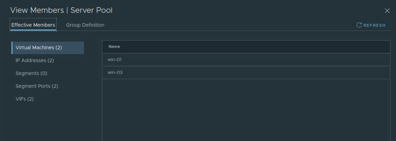
Before creating virtual service on NSX ALB Controller, I will create a dynamic security group in NSX-T based on VM name ‘win’. This security group will be used in server pool configuration of virtual service.

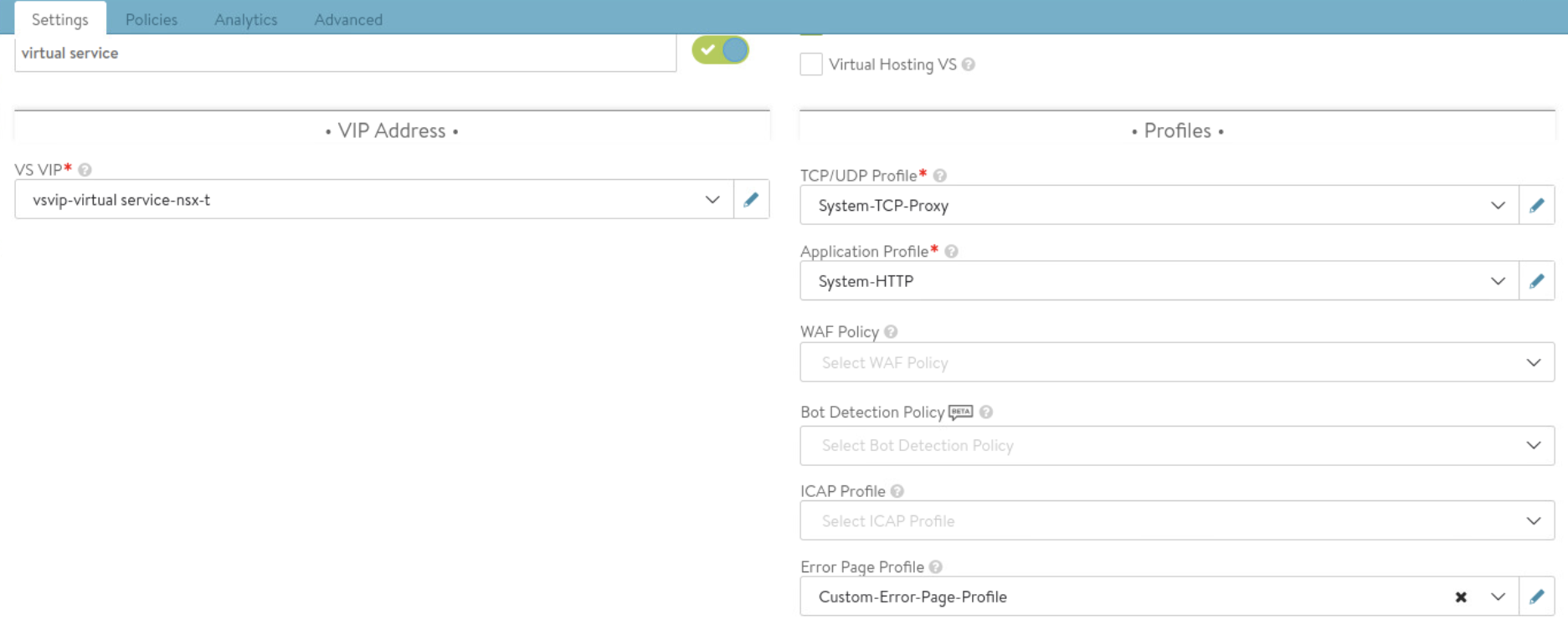
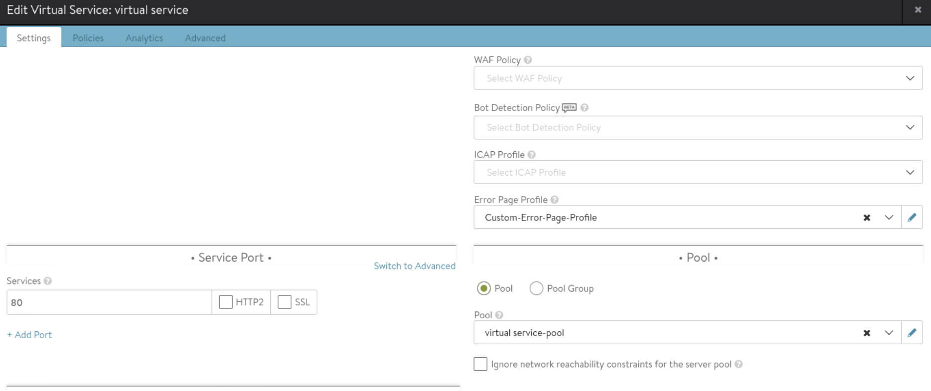
I will now create virtual service which will then trigger deployment of service engines based on the settings configured in SE group.
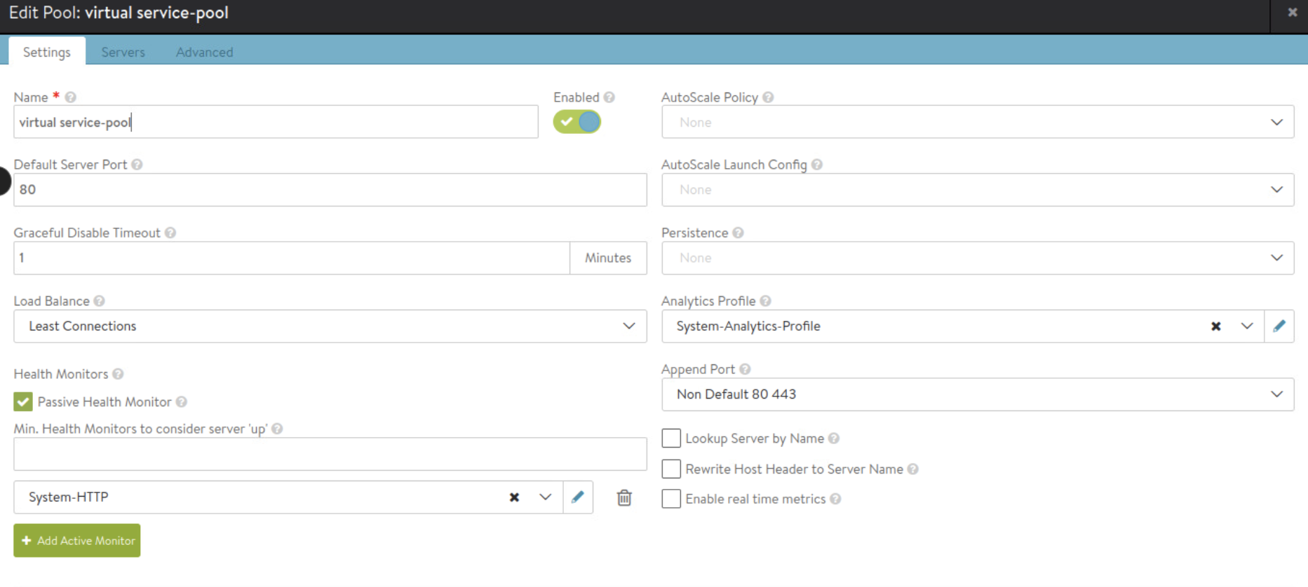
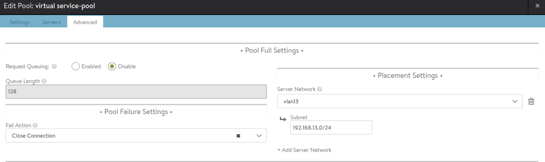
Create server pool while creating virtual service as shown below.
Server pool will use NSX-T security group as per below.

Continue with Virtual Service configuration:

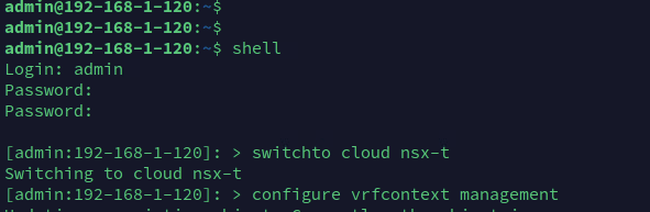
Next execute below commands on NSX ALB Controller to configure default route in management vrf of NSX-T cloud


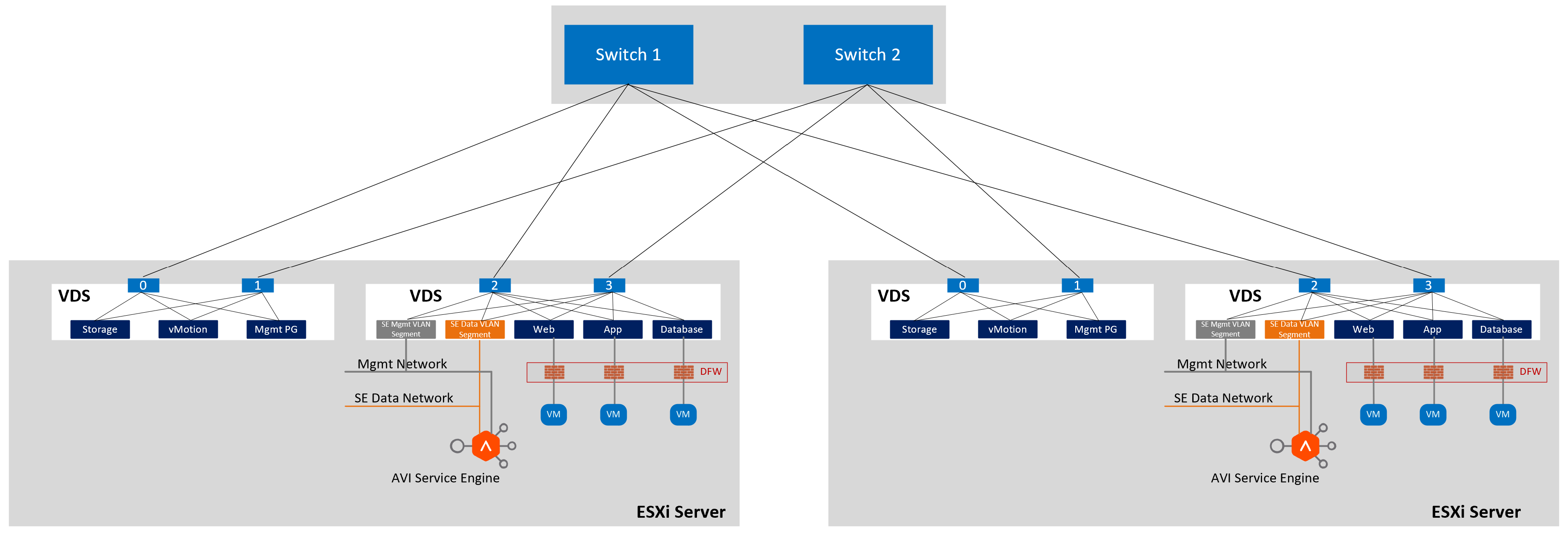
As shown in figure above, service engine has two networks – one for management and the other for data traffic.
The networks are created from NSX as NSX VLAN segments.
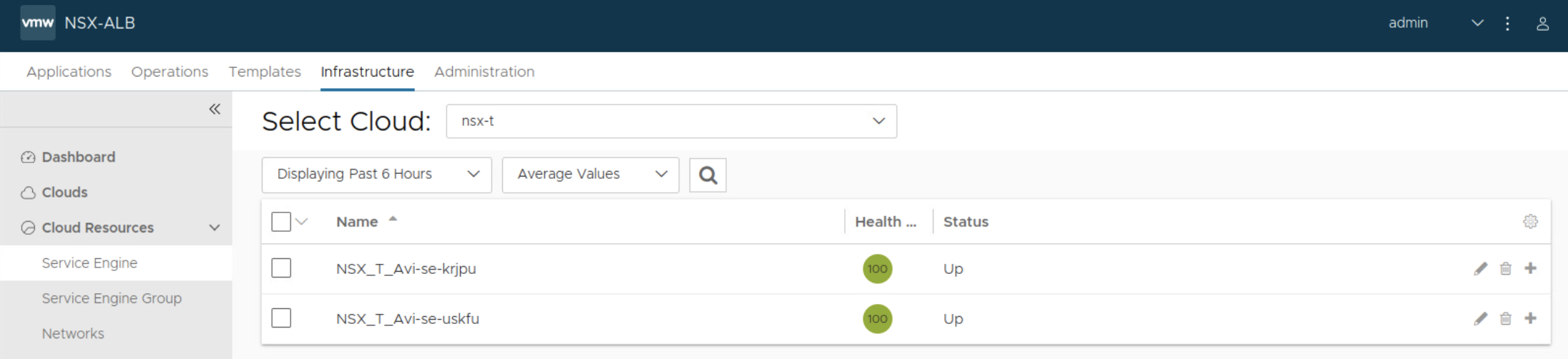
Validation:

Above logs capture:
- Client IP address
- Client browser
- Client OS Type which is Linux
- Virtual Service IP and port number
- Client RTT
- Server RTT
- Server IP and port number
- HTTP Request information
