
NSX Advanced Load Balancer Architecture ALB
NSX Advanced Load Balancer ALB provides L4+L7 load balancing services and is built on software-defined principles where easy scale out is provided. This approach removes the complexity of managing multiple physical appliances, gets rid of scale out issues when throughput requirements increase.
NSX ALB consists of two main components:
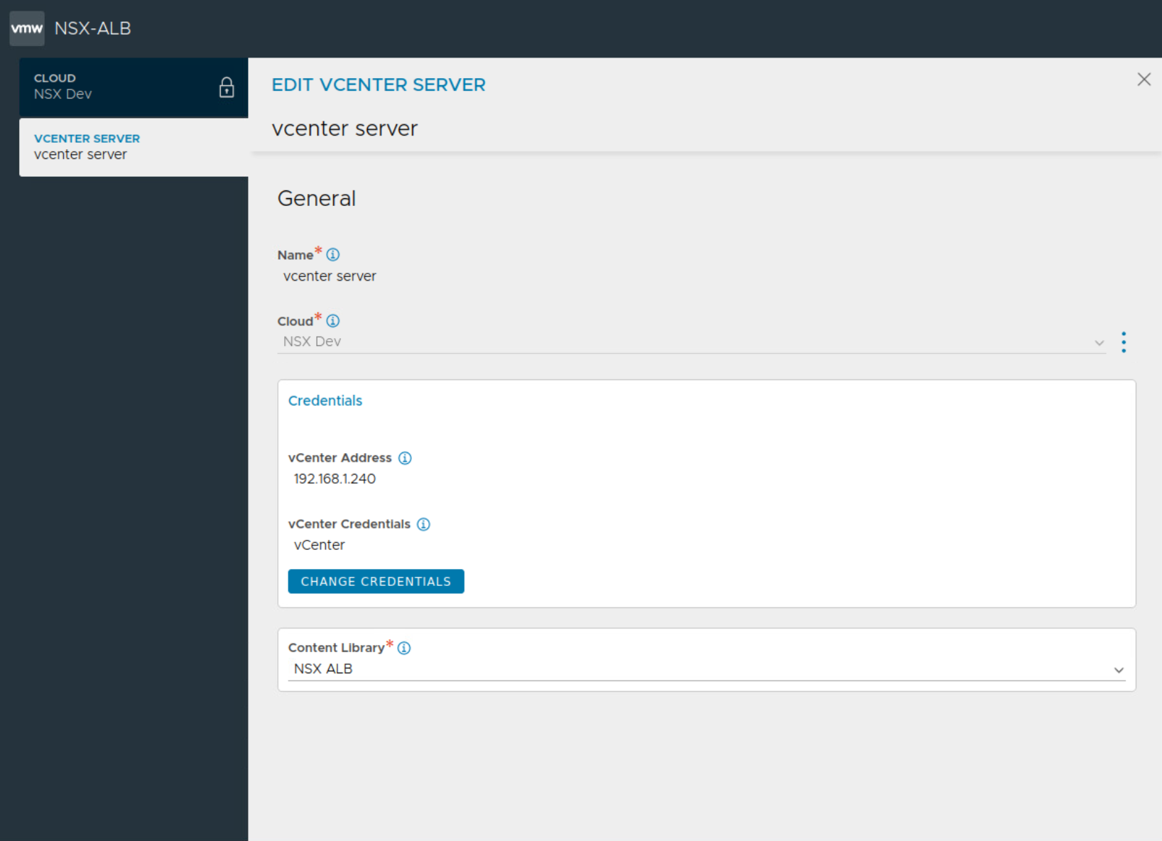
NSX ALB Controller: NSX ALB Controller is the central repository for the configuration and management. NSX ALB Controller is deployed in VM form factor and can be managed using its web interface, CLI, or REST API. The Controller implements the control plane. In write access mode of deployment, the controllers work with the underlying orchestrator such as vcenter server, NSX-T Manager to launch new SEs as needed when a new virtual service is configured for the first time.
Service Engines (SE): The Service Engines (SEs) are data plane engines that handle all data plane operations by receiving and executing instructions from the controller. Service engine virtual machines are auto deployed in write-access clouds where NSX-T clouds are configured on the NSX ALB controller. Such a integration requires NSX-T Manager information and vCenter server information to be passed to NSX ALB. Service engines provide data plane capabilities like server load balancing SLB, Global Server Load Balancing GSLB, Web Application Firewall WAF.
Controllers continually exchange information securely with the SEs and with one another. The health of servers, client connection statistics, and client-request logs collected by the SEs are regularly offloaded to the Controllers.
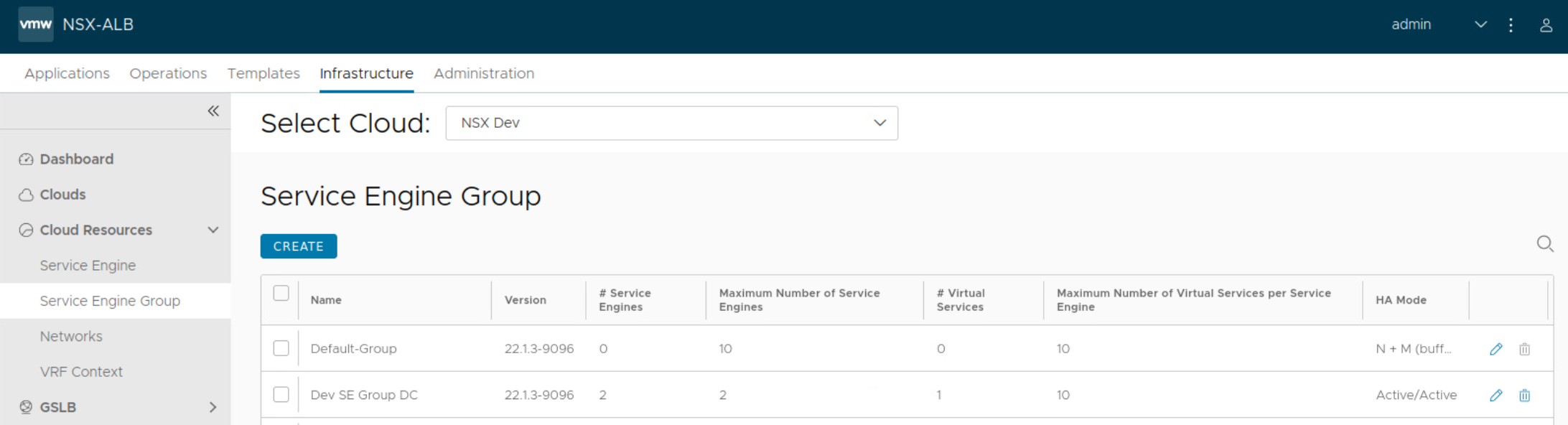
Service Engine Group:
Service Engines are created within a group, which contains the definition of how the SEs should be sized, placed, and made highly available. Each cloud will have at least one SE group. And multiple SE groups may exist within a cloud. One should note that SE group is selected while configuring virtual service alongside other required parameters such as server pool. This will place the virtual service on that specific service engine group.
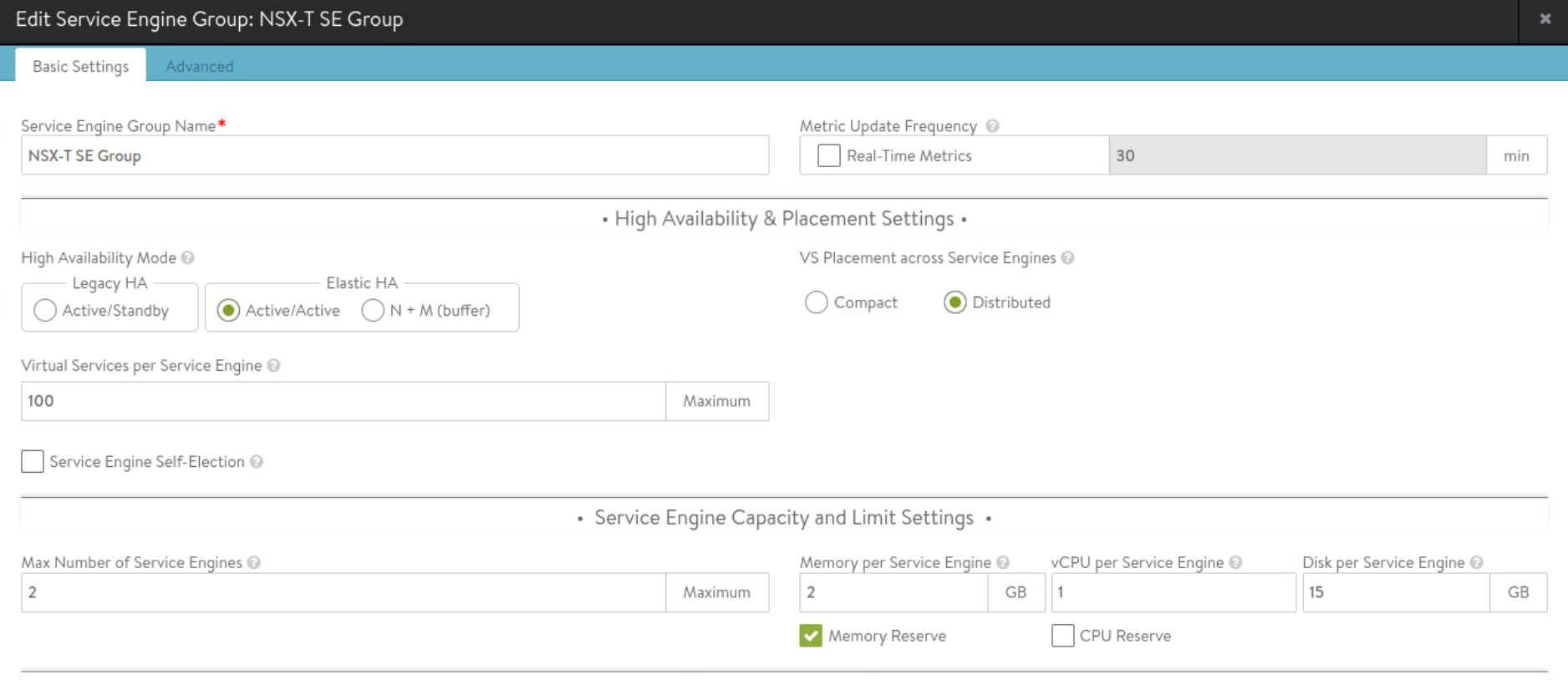
Importantly resource requirements like vCPU, memory and disk are configured under SE group settings. Allocation of vCPU will depend upon the available licenses, so it is important to size accordingly.
Keep in mind the following for CPU and memory allocation under service engine group:
CPU is a primary factor in SSL handshakes (TPS), throughput, compression, and WAF inspection. CPU is the primary constraint for both transactions per second and bulk throughput.
Memory allocation impacts concurrent connections and HTTP caching. Doubling the memory will double the ability of the Service Engine to perform these tasks
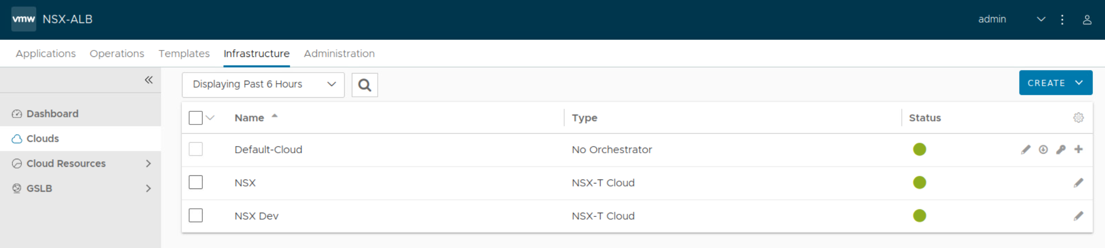
About Clouds supported on NSX ALB:
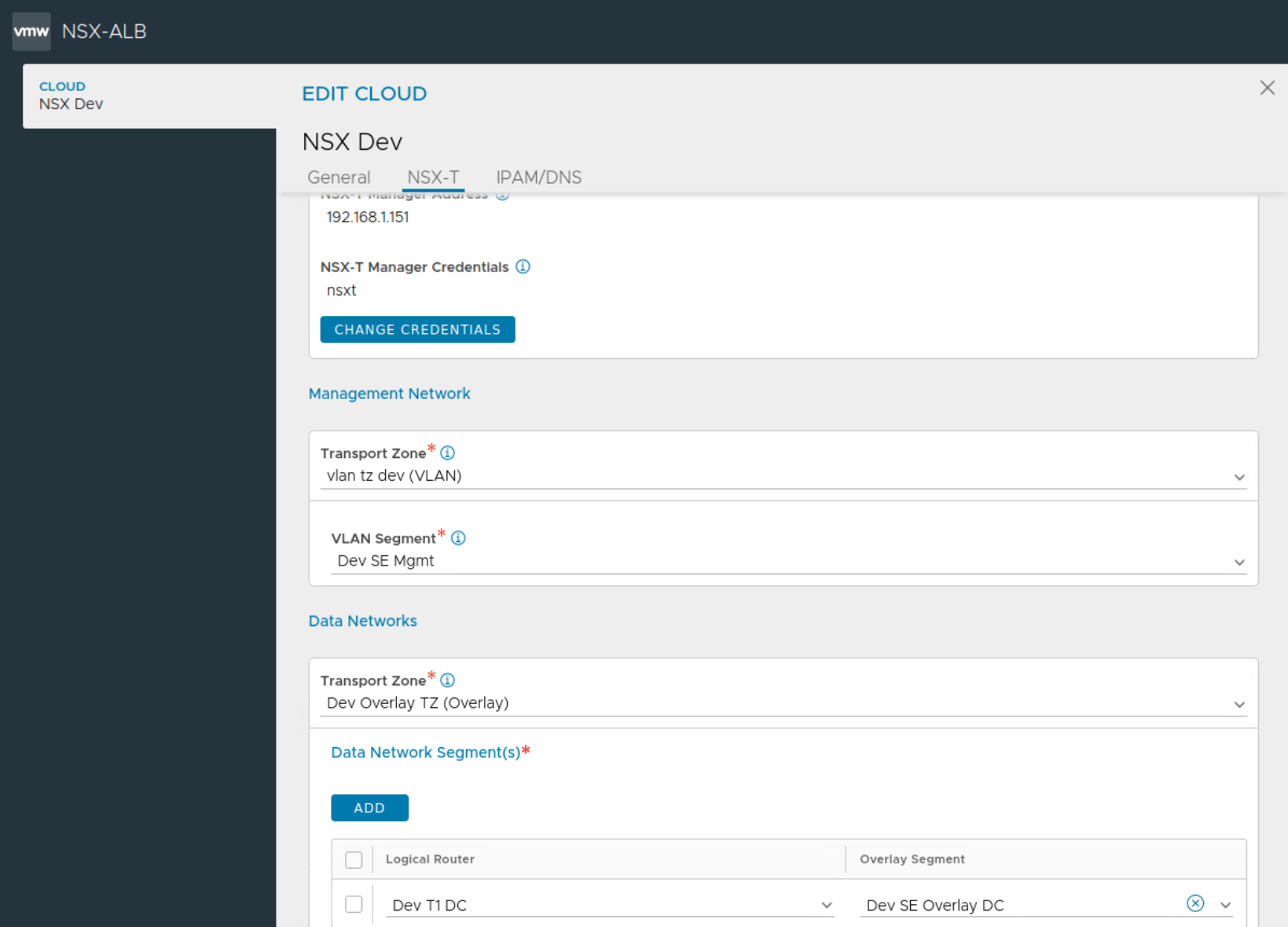
A Cloud is a container for NSX ALB service elements. Remember SE groups are always scoped to a particular cloud. An API connection is made between the controller and the orchestrator for that cloud for example vcenter server. Since each cloud is its own environment, networking and Avi Service Engine (SE) settings are maintained separately within each cloud. Multiple benefits are there for such clouds configured on NSX ALB such as auto creation of service engine VMs, life-cycle management of service engines. auto-plumbing of service engine networking.
NSX ALB supports varous clouds such as NSX-T cloud, VMware cloud, AWS, Azure, Linux.
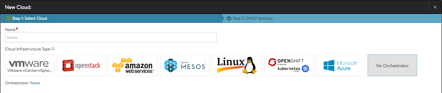
No access cloud is also possible for custom setups which cannot be fulfilled using clouds configured on NSX ALB. In such a deployment, administrators are responsible for the life cycle of SEs.
Some details about the capabilities of NSX-T cloud configuration on NSX ALB:
Two design options are there, either you place service engines in the same network as back end servers used in server pool configuration. This means that you will deploy more number of service engines based on the number of servers that need server load balancing, specifically number of networks where those back end servers are. This also means that sizing of service engines under SE group becomes critical, particularly vCPU allocation under SE group settings. vCPU allocation is important since it consumes ALB license.
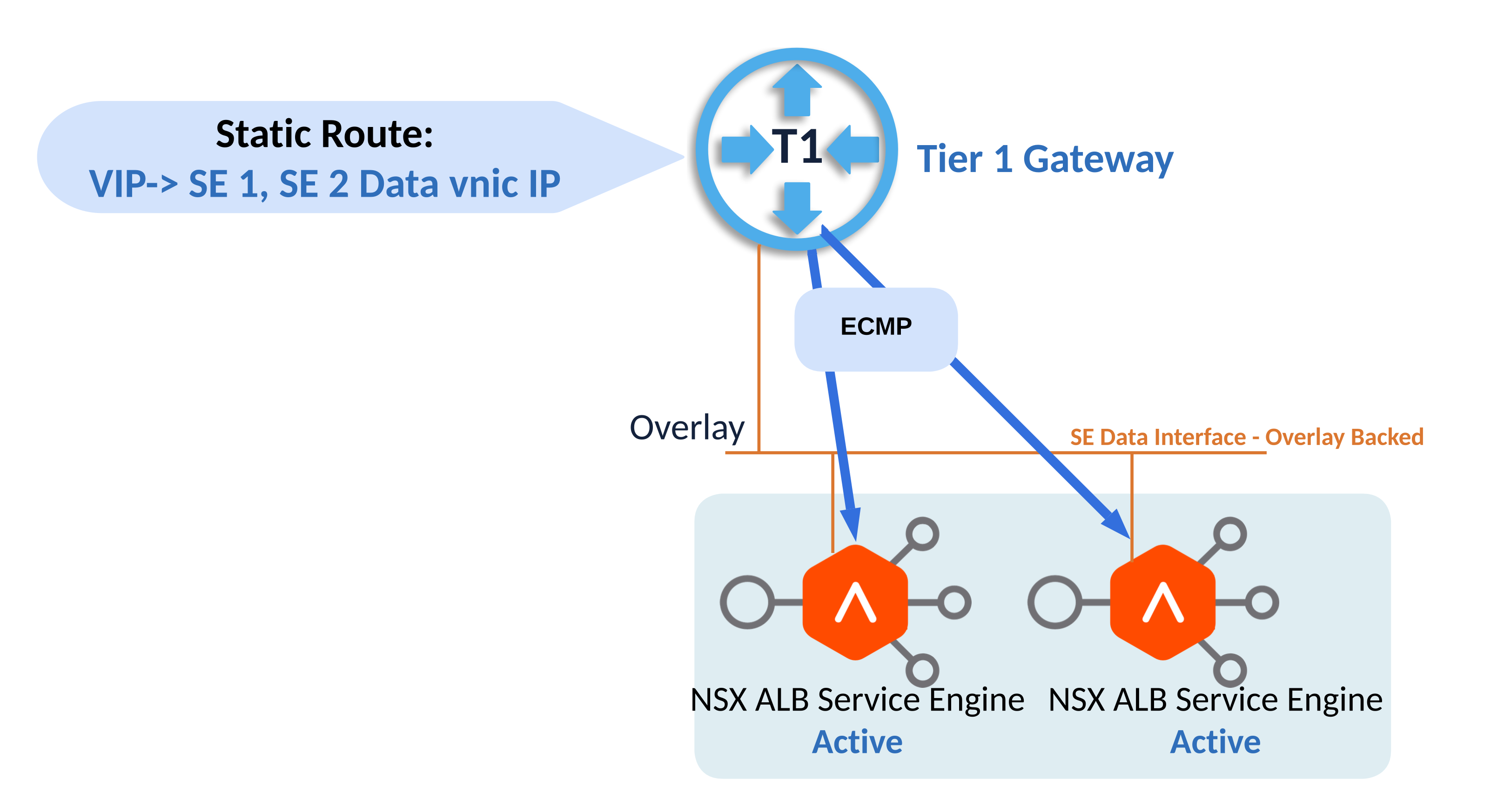
The other design option for placement of service engine will utilize a dedicated overlay network only for service engine data interface.
This design places data vnics of service engines on a dedicated overlay segment as shown above.
Once NSX-T cloud is setup properly, SE groups are configured, network pools are defined under networks and routing under each VRF context is done, then service engine is auto deployed once virtual service is configured.
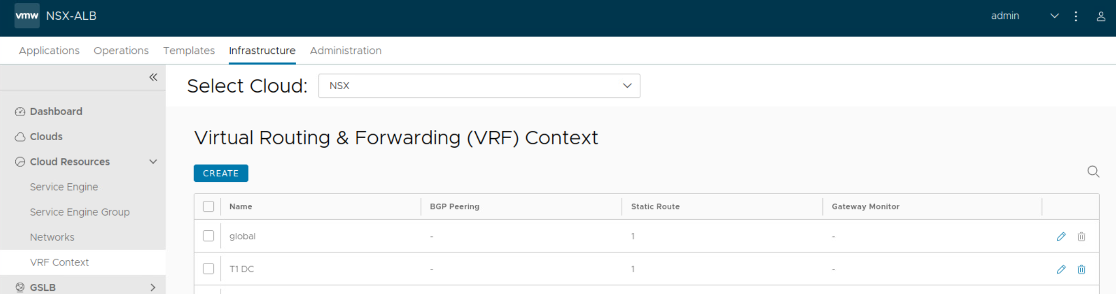
VRF Contexts in NSX-T Cloud:
NSX ALB automatically creates a VRF context for every tier-1 gateway selected during VIP network configuration. This is done because the Segments connected to different Tier-1s can have the same subnet.
A VRF must be selected while creating a virtual service so that the VIPs are placed on the correct segment and the VIP routes get configured on the correct tier-1 router.
Routing for NSX-T cloud configured on NSX ALB:
Static route is placed for the VIP automatically by ALB controller pointing towards IPs belonging to data vnic of service engines in case of Active-Active HA mode.
In case of Active-Active HA mode, this route is towards data interfaces of multiple service engines. But in the case of Active-Standby HA mode, this route is towards active service engine only.
Security automation using NSX-T cloud on NSX Advanced Load Balancer:
Creating NSX-T security Groups for SEs and Avi Controller management IPs is automated by the NSX-T cloud.
Security groups configured in NSX-T can be used in server pool configuration of NSX ALB. So server pool membership is auto updated in case security group is based on dynamic matching criteria such as NSX tags, VM name criteria.
Lab Setup
This Lab uses NSX-T Cloud with overlay networking.
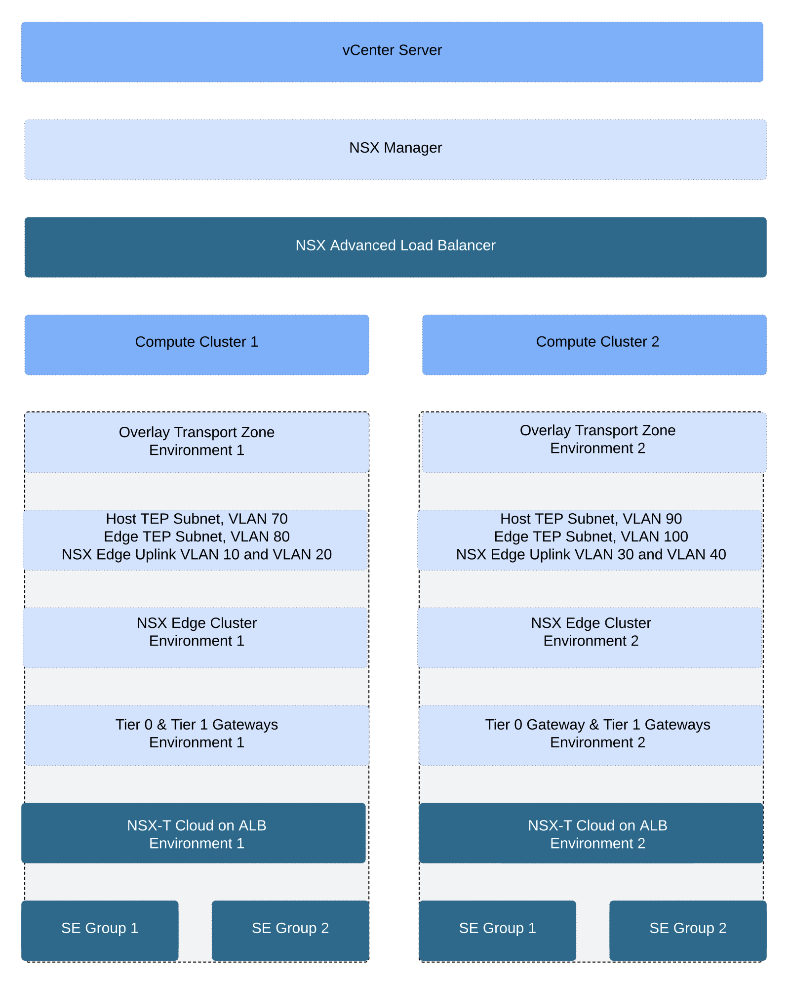
As shown in the figure above, the vsphere environment in this lab has single vcenter server with two workload clusters under it.
Both the compute clusters are prepared for NSX (overlay networking included) by single NSX manager.
Transport zone configuration in lab setup:
Two distinct overlay transport zones are used here in this lab and each overlay transport zone is associated with the corresponding compute cluster.
A little bit about transport zone construct in NSX-T:
Transport zones implies which hosts, clusters and, therefore, which VMs can participate in the use of a particular network, overlay segment or VLAN segment.
You can configure multiple transport zones based on requirements. One should note that a segment can belong to only one transport zone. You need to select appropriate transport zone during the configuration of segment in NSX-T.
Overlay segments live inside overlay transport zone, hence in this lab overlay segment created using overlay TZ of environment 1 will not appear on compute cluster 2 above. Also overlay segment created using overlay TZ of environment 2 will not appear on compute cluster 1. This also means that virtual network identifiers VNIs created for the overlay segments in environment 1 will be completely different from virtual network identifiers VNIs created in environment 2. NSX manager automatically handles the assignment of VNI for each overlay segment. There is no need of static allocation for the VNIs in NSX.
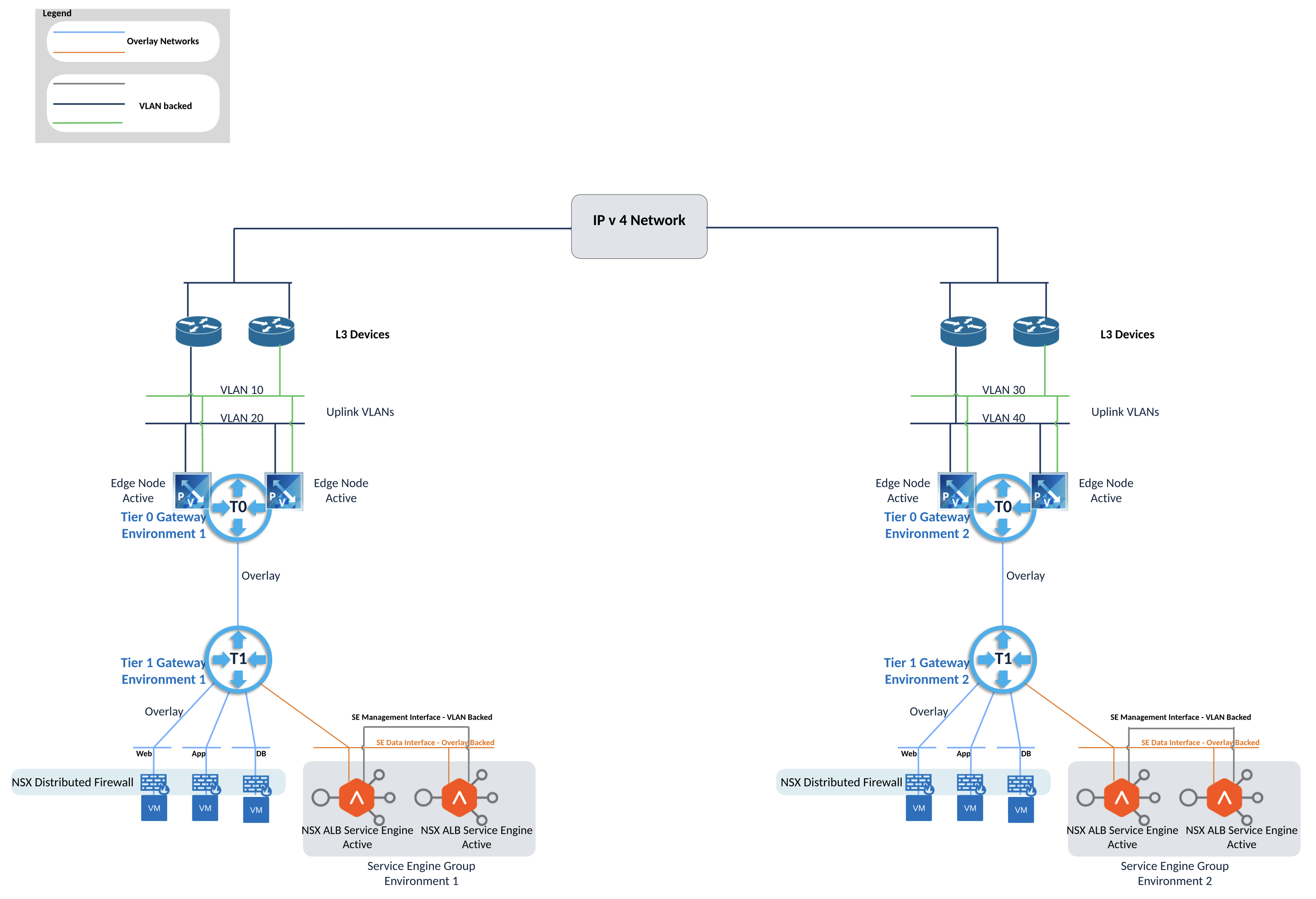
NSX Lab Topology
Above figure shows L3 topology for the lab setup.
Dedicated physical L3 devices, NSX gateways and NSX ALB service engine groups are utilized for each environment, environment 1 is on the left hand side and environment 2 setup is on the right hand side.
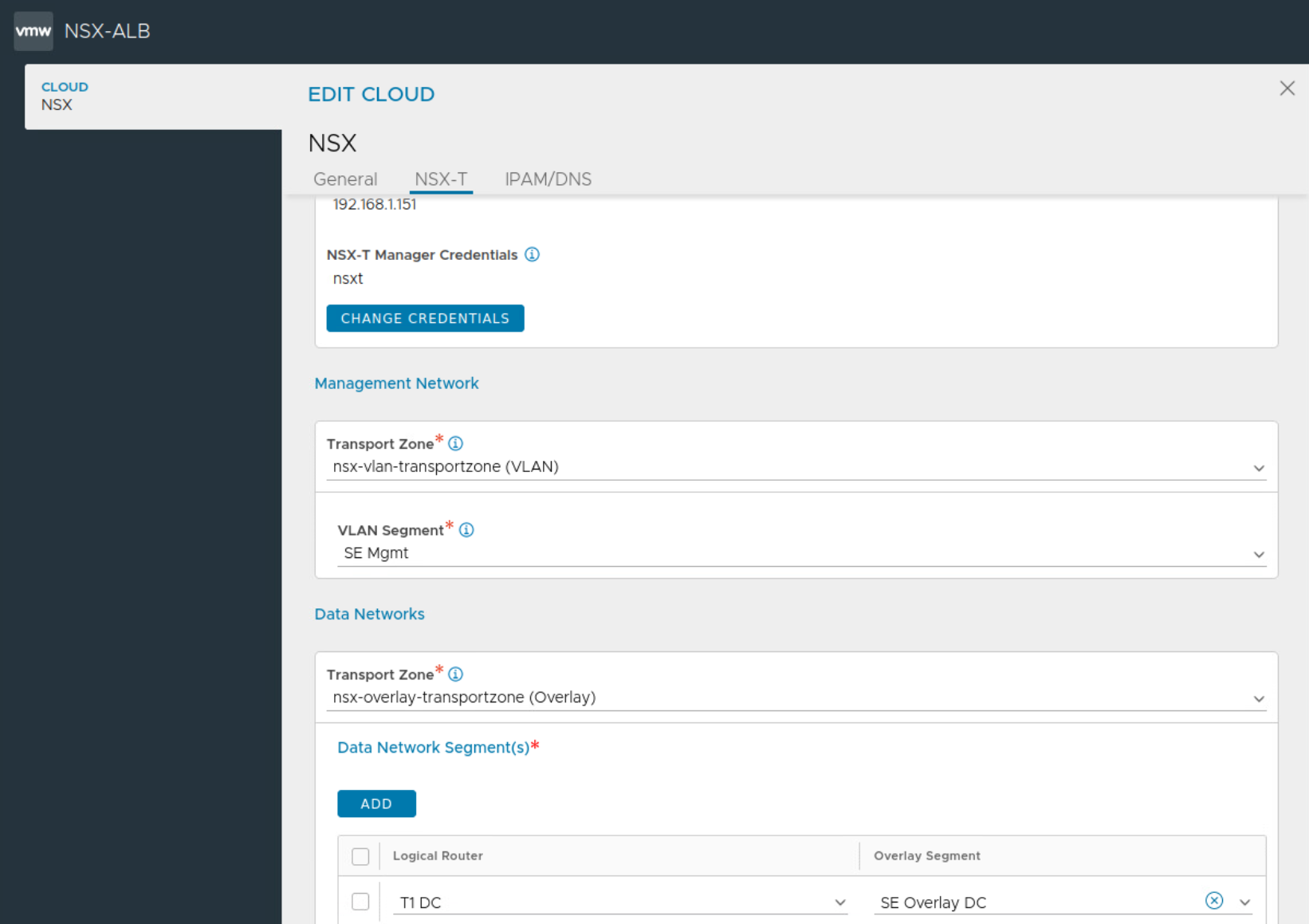
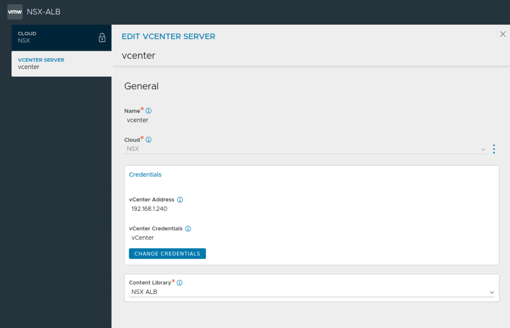
We’ll begin by creating the two NSX-T Clouds on NSX ALB
Next configure SE group or multiple SE groups if needed. Pay careful attention to procured number of NSX ALB licenses during this step and utilize vCPU allocation accordingly on the SE group.

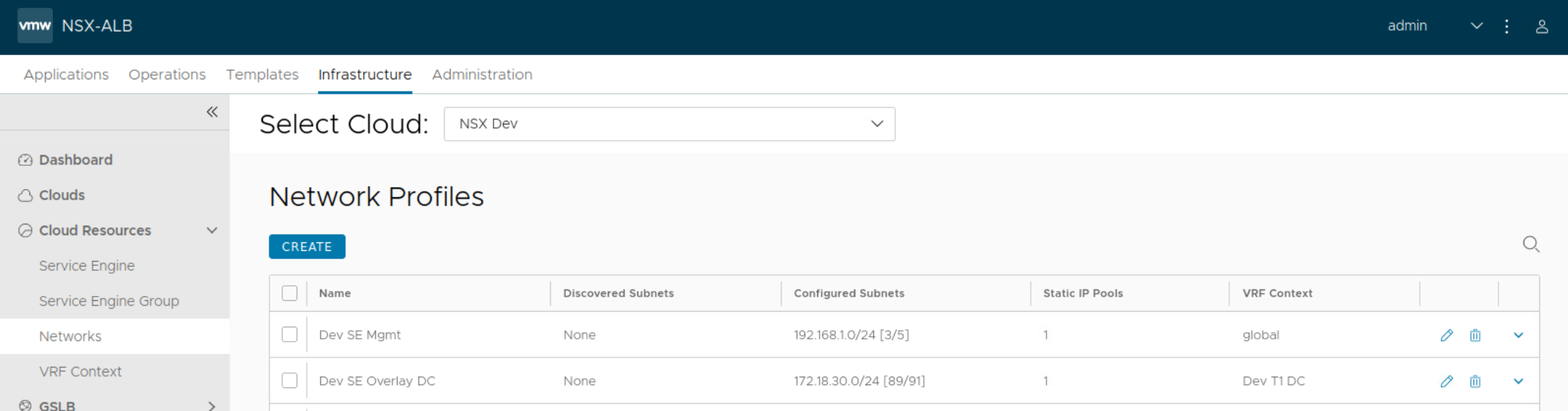
Auto discovery of networks is done on NSX ALB in the cases of NSX-T Cloud, static IP pools are then added.
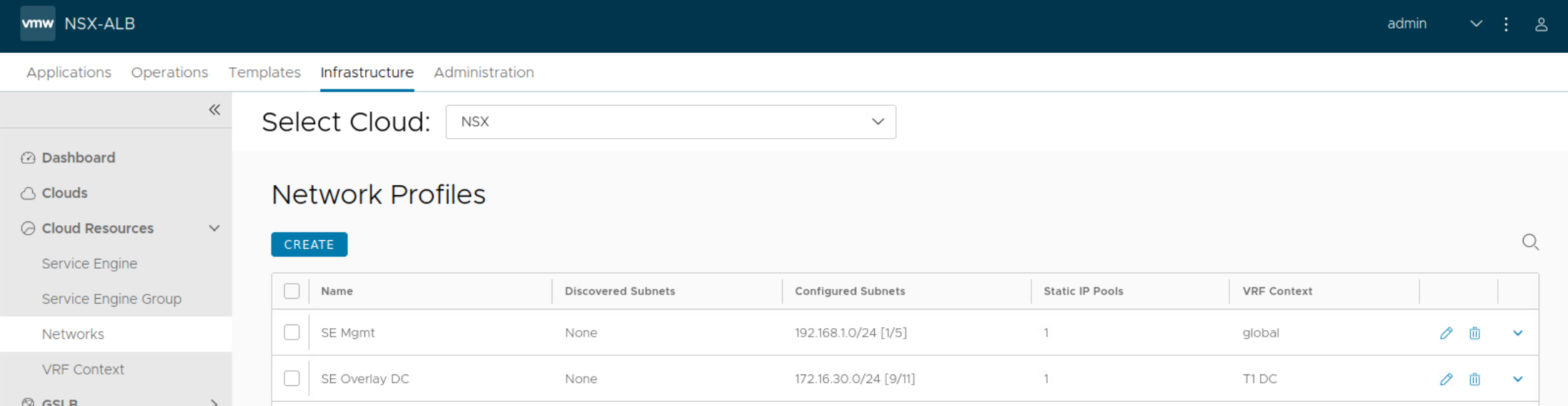
Static IP pools is configured for each auto discovered network.
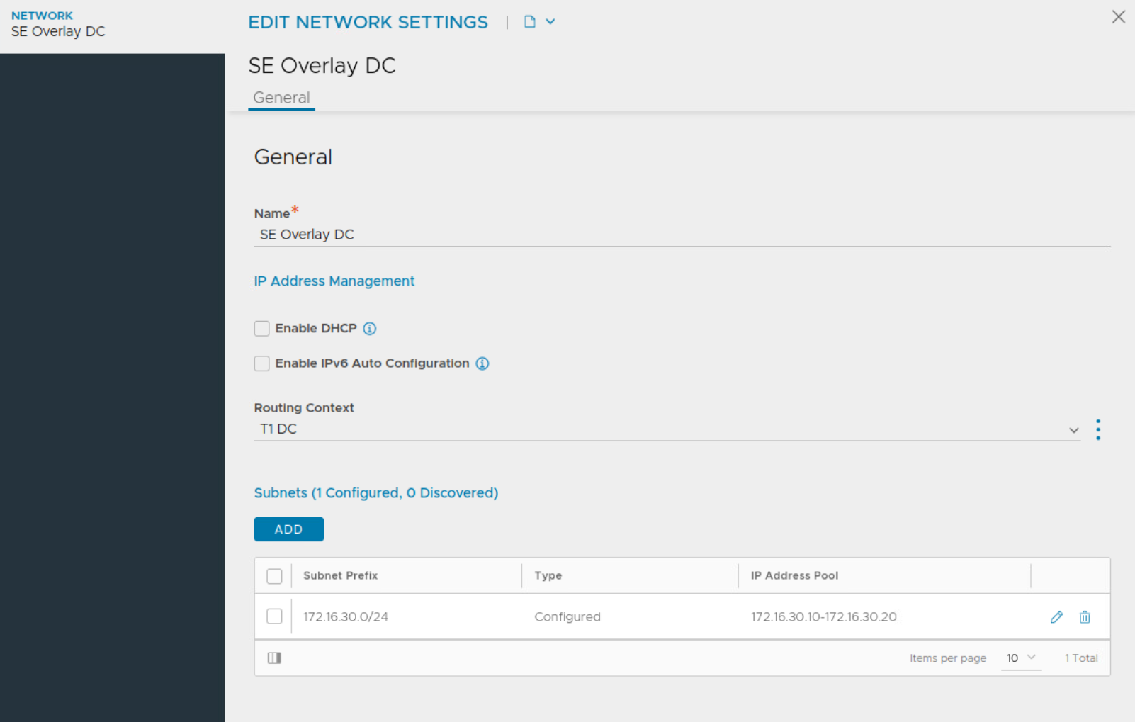
Repeat this above step for other networks and assign static IP pools under remaining auto discovered networks.
NSX ALB also automatically allocates VRF context for each Tier 1 Gateway in your setup.
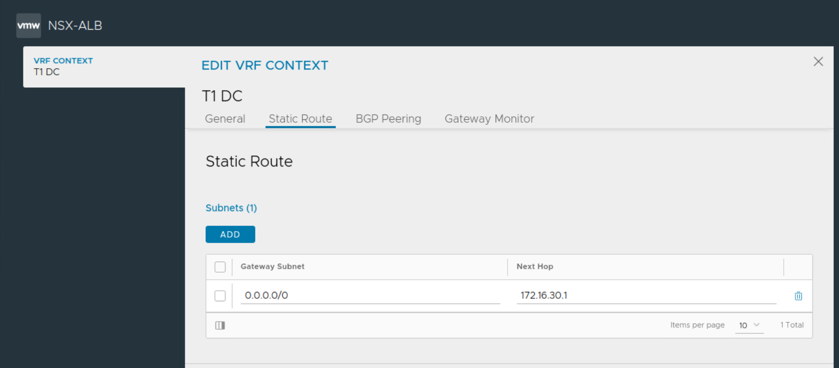
Ensure static route is configured under each auto discovered VRF on NSX ALB towards the gateway IP address for that specific network.
Create the other NSX-T Cloud
Using above principles, create the second NSX-T Cloud on NSX ALB
Next configure server pools and the VIPs

Notice the selection of Tier 1 Gateway during the configuration of server pool.
Next create VIPs which will be utilized on the virtual service.
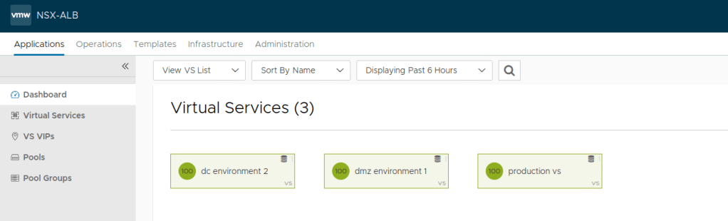
Now go ahead and create your virtual service.
Next select appropriate VRF under the cloud and configure virtual services for the various apps as needed. Select appropriate SE group while creating the virtual service.
Useful Technical References:
VMware NSX ALB Documentation
https://docs.vmware.com/en/VMware-NSX-Advanced-Load-Balancer/index.html
ALB Architecture
https://avinetworks.com/docs/22.1/architectural-overview/
NSX-T Design Guide for Avi
