
Similar to routers with VRF lite feature, NSX Tier 0 Gateway supports VRF gateway feature which allows multiple VRF gateways to exist under the parent Tier 0 Gateway.
VRF gateways in NSX save CPU, memory and storage resources because multiple VRF gateways are associated/mapped with the same NSX edges as those of the parent Tier 0 Gateway. And there is no need to deploy additional NSX edges (which will then increase CPU, memory and storage requirements) for separate Tier 0 gateways.
Sample topology without VRF gateway use case:

In the above topology, multiple Tier 0 Gateways are deployed per firewall zone, a total of 6 NSX edges are shown. These zones on the firewall can be for different environments and for isolation purpose from physical firewall perspective. Since overall multiple Tier 0 gateways are needed and a Tier 0 Gateway is needed per firewall zone, this means that additional NSX edges will be deployed consuming underlying infrastructure CPU, memory and storage. This is because one NSX edge supports one parent Tier 0 gateway. It is worth highlighting that since dedicated NSX edges are deployed per environment, north-south throughput will be based on the number of NSX edges mapped on each Tier 0 gateway. A Tier 0 Gateway with Active/Active high availability mode can have up to 8 NSX edges for higher north-south throughput use-case.
And now we will try to map the above topology using NSX VRF gateway use-case:

Above topology shows how one can maintain firewall zoning using separate interfaces on physical firewall facing each of the environments and utilize NSX VRF gateway use-case to peer each VRF gateway with upstream firewall. Note that only two NSX edges are sufficient in this case as compared to the previous topology where there were 6 NSX edges. This VRF gateway use-case has two NSX edges which means that north-south throughput will be handled by these two NSX edges in case of Active-Active high availability mode on the Tier 0 Gateway.
Each VRF gateway can its own uplink or uplinks towards the physical network. This means that each VRF gateway will have its own uplink VLAN towards a firewall. Or in the case of physical routers, each VRF gateway will have its own uplink VLANs (two VLANs for two upstream physical routers) towards the two physical routers.
VRF gateway will inherit NSX edge cluster and HA mode of the parent Tier 0 Gateway.
From NSX release 4.1.0 onwards, now it is possible to configure a different BGP ASN (Autonomous System Number) per Tier-0 VRF Gateway. Prior to this release, BGP AS number on VRF gateway would inherit the BGP AS number of parent Tier 0 gateway.
Also note that you can have more than one parent Tier-0 gateway with VRF gateways enabled. So you flexibility in terms of customizing the SDN topology based on requirements.
Below figure shows desired east-west and north-south traffic flows in this sample topology.

Some important pre-requisites before configuring NSX VRF gateway:
The parent Tier-0 gateway needs to be created before the tier-0 VRF gateway is configured.
The parent Tier-0 gateway needs to have an external interface before you create an external interface on the Tier-0 VRF gateway.
VLAN tagging (802.1q) is used to differentiate traffic among VRFs.
For the deployment and configuration, you can check this blog post of mine.
In this post, we will also cover traffic flows in the context of NSX VRF gateway and try to understand how Distributed Router DR and Service Router SR is instantiated:

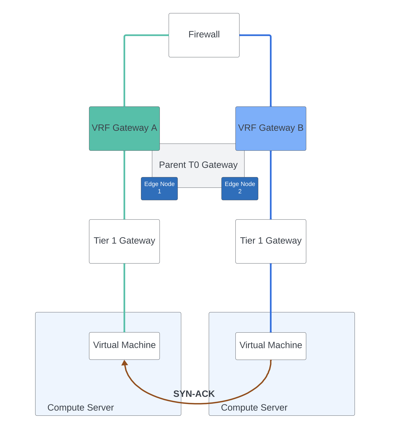
Above topology references two VRF gateways which are created out of a parent Tier 0 Gateway. The parent Tier 0 Gateway is mapped with NSX edge cluster consisting of two NSX edges. Each VRF gateway has its own DR only Tier 1 Gateway under it. There is no NSX edge cluster mapped on Tier 1 Gateway in this example. Two virtual machines behind two different Tier 1 Gateways are in the process of establishing a TCP 3 way handshake. Above figure shows a TCP SYN packet from one VM to the other.

And now we discuss the response of the VM back to the initiator using TCP SYN-ACK packet.

For the deployment and configuration, you can check this blog post of mine.
