
- Provides single pane of glass for managing networking and security constructs of more than one location.
- Allows stretching of overlay networks between locations
- VM mobility between locations using the same IP address. This is possible because NSX Federation ensures same network is available across multiple locations.
- Recover VMs in disaster recovery location using the same IP address because same network is available in DR location. NSX Federation ensures same network is available across locations and VMware Site Recovery Manager can be used to protect VMs and recover those in recovery location.
- Retain security posture of virtual machine when VM moves from one location to the other location. VMware NSX Distributed Firewall is used for this.
NSX Federation key concepts such as below are covered here in this link:
Global Manager GM: NSX manager VM which provides single pane of glass from where you can manage networking and security constructs related to more than one location.
Global Tier 0 Gateway: Tier 0 Gateway which is configured from Global Manager, can be stretched gateway which is stretched across multiple locations or can be non-stretched (specific to one location only).
Global Tier 1 Gateway: Tier 1 Gateway configured from Global Manager, again can be stretched gateway which is stretched across multiple locations or can be non-stretched (specific to one location only).
Remote Tunnel Endpoint RTEP interface: This interface is used for Geneve encapsulation/decapsulation of inter-location traffic, traffic which moves between locations.
This blog post discusses NSX Federation use case where the upstream physical firewall is clustered across two locations.
Below is the vSphere setup:
Shared compute and edge cluster design is used whereby NSX edges are deployed on NSX prepared vSphere clusters. This means that NSX edges will reside on the vSphere cluster which also hosts workload virtual machines. And the workload virtual machines will eventually be connected to stretched NSX overlay network.
Management cluster will be used to place NSX managers viz. NSX Local manager, NSX Global Manager. vCenter server also resides on the management cluster.

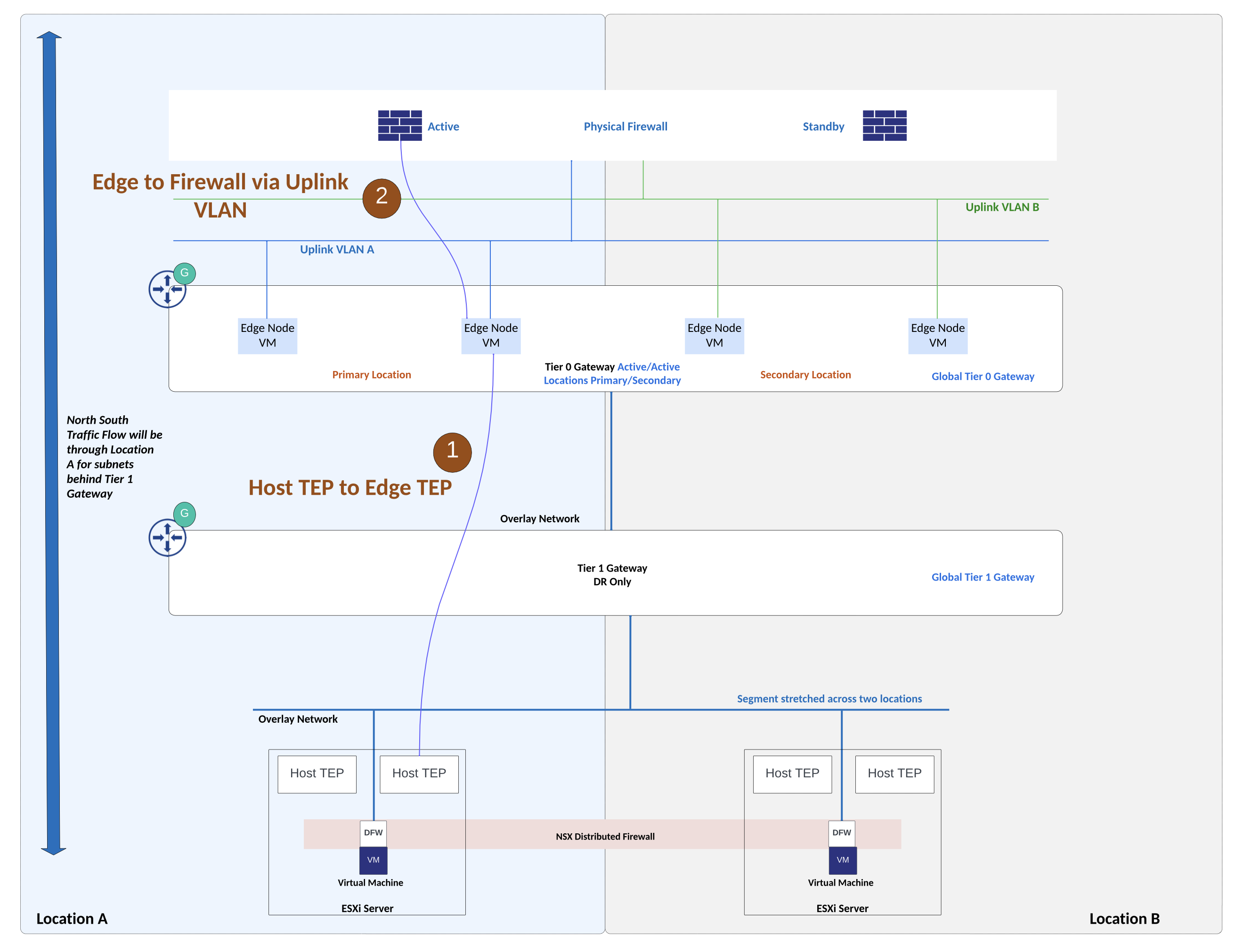
The setup being discussed in this post has a use case where Global Tier 0 Gateway of NSX Federation is peering with physical firewall in Active/Standby high availability mode. Upstream physical firewall set up is such that the active firewall appliance is in location A while the standby firewall appliance is in location B.

Details about the setup:
Upstream physical firewall has active firewall appliance in location A and standby firewall appliance is placed in location B. Networks related to physical firewall high availability are stretched between locations using underlay physical network. Underlay physical network is able to stretch VLAN networks between the two locations. Appropriate WAN links from service provider can be deployed for this L2 stretching using VLAN. NSX overlay network is stretched between locations using NSX Federation.
Two VLANs on the physical firewall which are facing NSX edges belong to a security zone on upstream firewall. These VLANs are stretched between locations for firewall failover to occur seamlessly.
Firewalls such as Palo Alto firewalls allow logical grouping of physical/virtual interfaces into a security zone. An interface on the firewall must be assigned to a security zone before the interface can process traffic. A security zone can have multiple interfaces of same type (L2, L3, tap interface) under it. Traffic can flow freely within a zone but traffic cannot flow between different security zones unless a security policy rule is configured to permit traffic. Security policy rules will reference source zone and destination zone.
Also check this link for Palo Alto firewall interface and zone configuration.
As shown in figure above, VLAN A and VLAN B (peering VLANs between NSX edges and upstream firewall) belong to the same security zone on the upstream firewall.
VLAN A is used between NSX edges in location A and upstream physical firewall. VLAN B is used between NSX edges in location B and upstream physical firewall.
Two NSX edges are deployed in each location, these edges in each location will handle cross location traffic (east-west) using RTEP interface on NSX edge.
Egress traffic from NSX: During normal operations, NSX edges in Location A will handle north-south traffic. This is influenced by Global Tier 0 Gateway configuration which is Active/Active Locations Primary & Secondary. With this Global Tier 0 gateway configuration, traffic from NSX subnets will leave via NSX edges in location A.
Ingress traffic towards NSX: BGP AS path prepending is used for e-BGP peering between NSX edges in location B and upstream firewall. Using this configuration, traffic towards NSX subnets from physical firewall will prefer NSX edges in location A.
Routing Setup:

Above topology shows routing setup. Private BGP AS number is allocated to the Global Tier 0 Gateway. Upstream physical firewall is in a different, private BGP AS number. Physical firewall needs to advertise default route towards NSX edges. And NSX prefixes will be advertised by NSX edges towards physical firewall. As shown in figure above, BGP AS Path prepending configuration is applied over e-BGP peering between NSX edges in location B and upstream firewall. Because of this configuration, ingress traffic from physical firewall towards NSX subnets will prefer NSX edges in location A.
Egress Traffic Flows from NSX subnets:
Egress traffic flow follows the configuration of Global Tier 0 Gateway which is Active/Active with locations primary and secondary. With this configuration on the Global Tier 0 gateway, egress traffic from NSX will be handled by NSX edges in primary location which is location A in this example.

Ingress traffic towards NSX subnets:


