
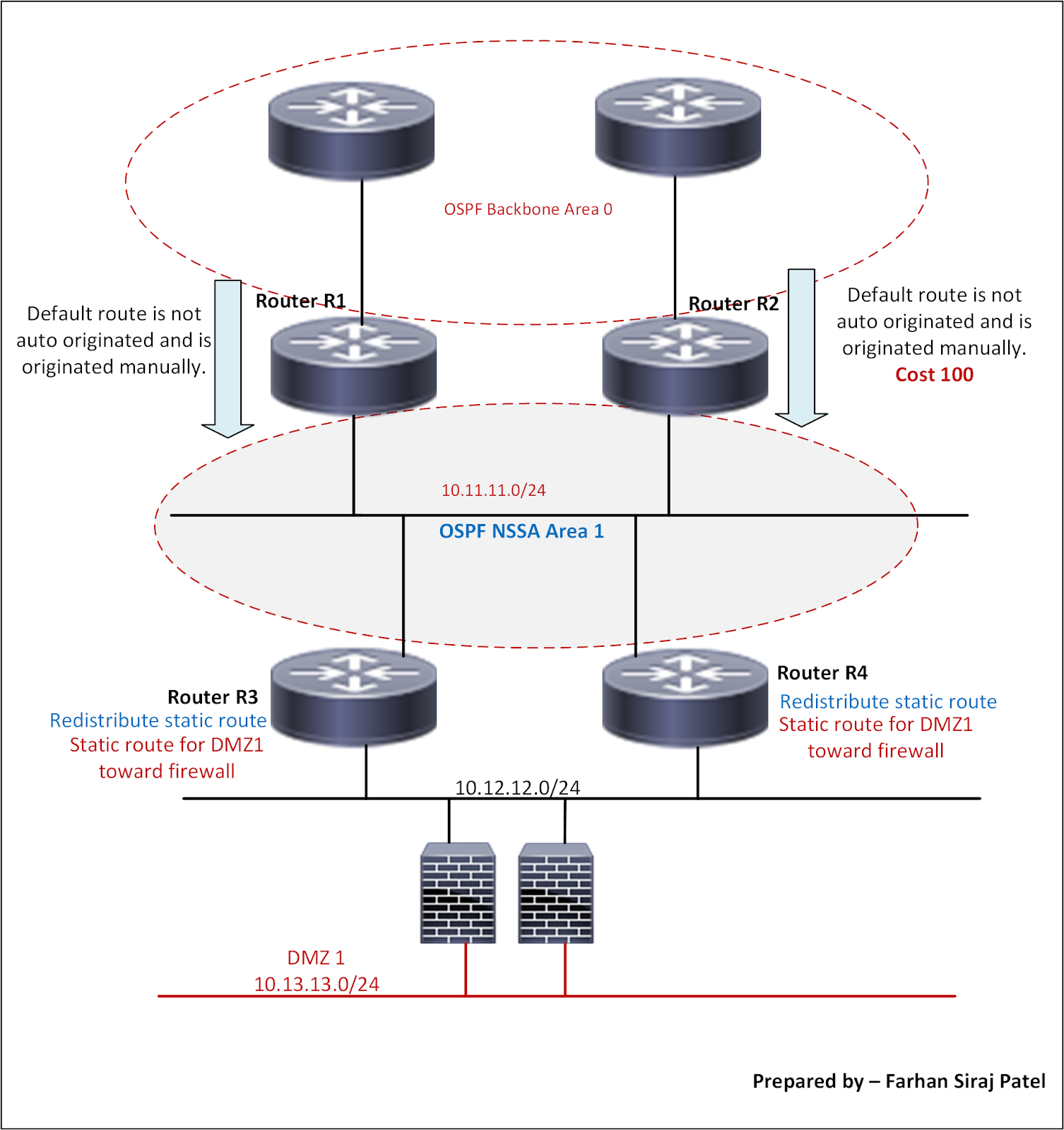
In the topology above, routers R1 and R2 are the ABRs interfacing with backbone area 0
Area 1 in this topology has been configured as NSSA this time. My earlier topology referenced a Totally NSSA area.
As mentioned earlier, NSSA configuration in OSPF allows redistribution to occur within the NSSA area.
These redistributed prefixes are Type 7 LSAs and are converted to Type 5 LSAs as they are injected in area 0 by one of the ABRs interfacing area 0
Router with higher router ID is elected to do this translation where there are multiple ABRs interfacing backbone area 0
Like stub area, Type-5 external LSAs are blocked from entering the NSSA area.
Compared to Totally NSSA, area configured as NSSA will not filter Type 3 LSAs and will only filter Type 4/Type 5 LSAs.
Compared to Totally NSSA, area configured as NSSA will not filter Type 3 LSAs and will only filter Type 4/Type 5 LSAs.
As opposed to Totally NSSA; in the case of NSSA, the default route is not auto injected.
And this needs to be injected manually using command area
nssa default-information-originate
nssa default-information-originate
===================================
Area specific configuration on routers R1, R2, R3 and R4 is as below
Configuration on Router R1
Conf t
Router ospf 1
Area 1 nssa default-information-originate
Configuration on Router R2
Conf t
Router ospf 1
Area 1 nssa default-information-originate metric 100
Configuration on Routers R3 and R4
Conf t
Router ospf 1
Area 1 nssa
For demonstration purpose, note in the above configuration of Router R2, we have increased the metric of default route to 100
This will force traffic from routers R3 and R4 to follow the default route of Router R1 since route from R1 has lower metric.
We are just trying to cover this use-case whereby you can force the traffic through one of the upstream routers in case there is a better WAN link there.
Below output shows default route on router R4
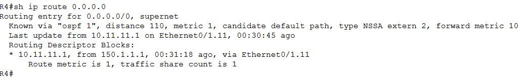 |
| Default Route on Router R4 |
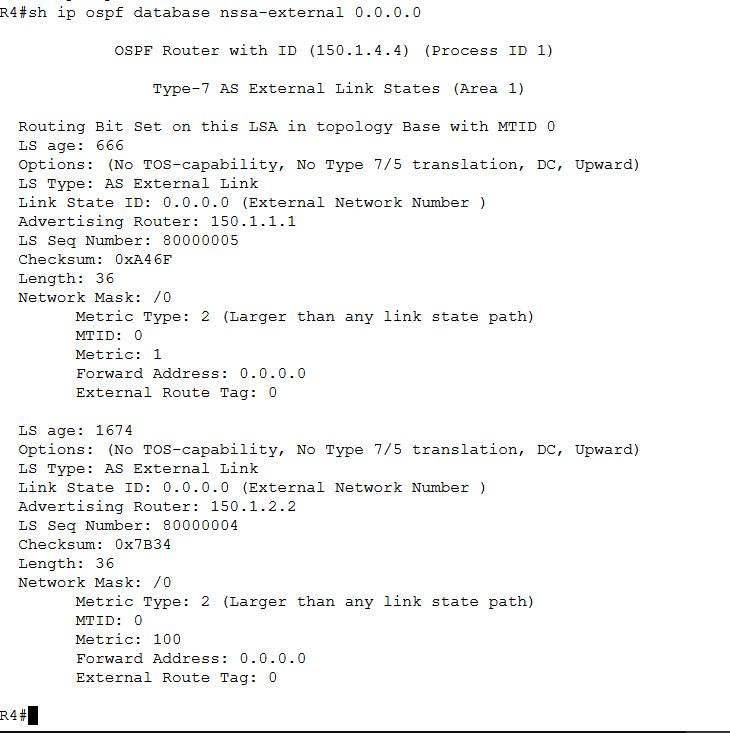
Below output shows clearly that metric through Router R1 is lower as compared to Router R2
=======================================
If you want the traffic moving from R3/R4 towards backbone area 0 to be load balanced across R1/R2, then there is no need to increase the metric of default route on R1/R2
In that case, OSPF topology information for default route on Router R4 will be as below.

