
I have covered a couple of NSX-T Federation blogs earlier.
In this blog, we will setup OSPF in the underlay network as opposed to BGP. And we will setup stretched T0 Gateway with Active-Active HA mode. We will be using additional redistribution control from NSX end to ensure traffic ingresses/egresses via physical gateway in one location.
Here, I am using OSPF backbone area 0 but in practical designs one should consider multiple OSPF areas for large enterprise networks.
Technology Overview for NSX-T Federation:
NSX-T Federation provides networking and security across multiple locations.
With NSX Federation, you can manage multiple NSX-T Data Center environments with a single pane of glass view, create gateways and segments that span one or more locations, and configure and enforce firewall rules consistently across locations.
NSX segments (overlay networks) can span multiple locations.
Span of NSX segment is equal to the span of the attached NSX gateway. These overlay networks of NSX can be connected to Tier 0 Gateway or Tier 1 Gateway ( in case of multi tier routing topology). Multi tier routing topology is recommended because it gives flexibility to use stateful services on Tier 1 Gateway if needed.
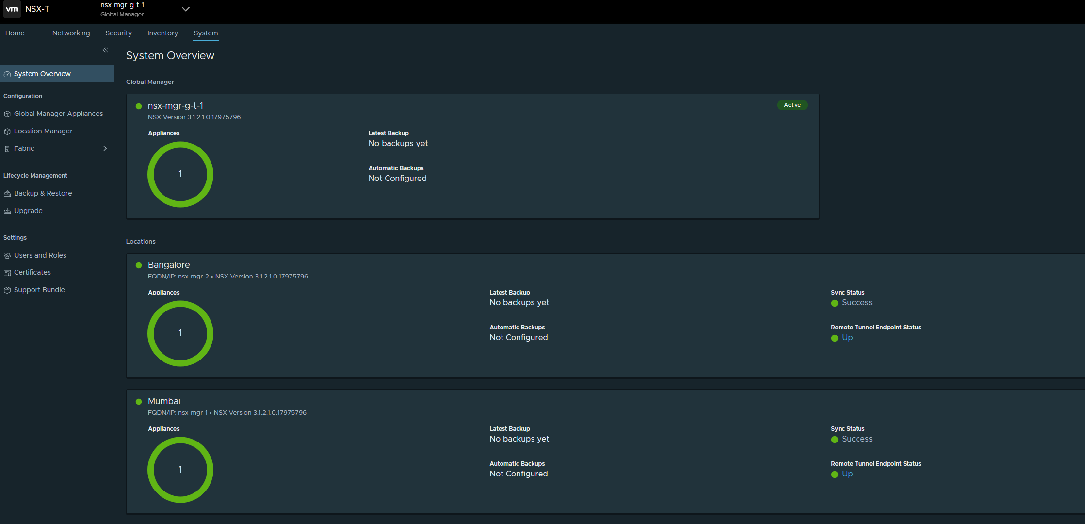
Global Manager – provides a centralized management for networking and security services of multiple locations.
Global Manager Active instance (made of 3 Global Manager VMs) is placed in one Location.
And the Standby Global Manager instance (made of 3 Global Manager VMs) is placed in another location.
In addition to Global Managers, there are NSX-T Local Managers which are used to:
- Configure Transport Zones in a location
- Configure Transport Node Profiles which are used to install NSX on servers
- Install NSX on servers in a location
- Deploy edges and configure NSX on those NSX edges
NSX Gateways in the case of Federation can have a span which covers one location or can be stretched where the gateway spans multiple locations.
Tier-0 gateways can have one of the following configurations:
- Non-stretched tier-0 gateway.
- Stretched active-active with primary and secondary locations.
- Stretched active-active with all primary locations.
- Stretched active-standby with primary and secondary locations
The different topologies possible are documented here
In the case of NSX Federation, NSX edges (which mainly handle north-south traffic in the software defined data center and also provide services like NAT, gateway firewall) have Remote Tunnel Endpont Interface RTEP. This interface handles cross location traffic between different data centers. Essentially the cross site tunnels are established by using this RTEP interface.
Edge TEP interface will have tunnels between itself and TEP interfaces on hosts/servers within the same location. With NSX Federation, there will be no Geneve tunnels between two servers which are in different locations.
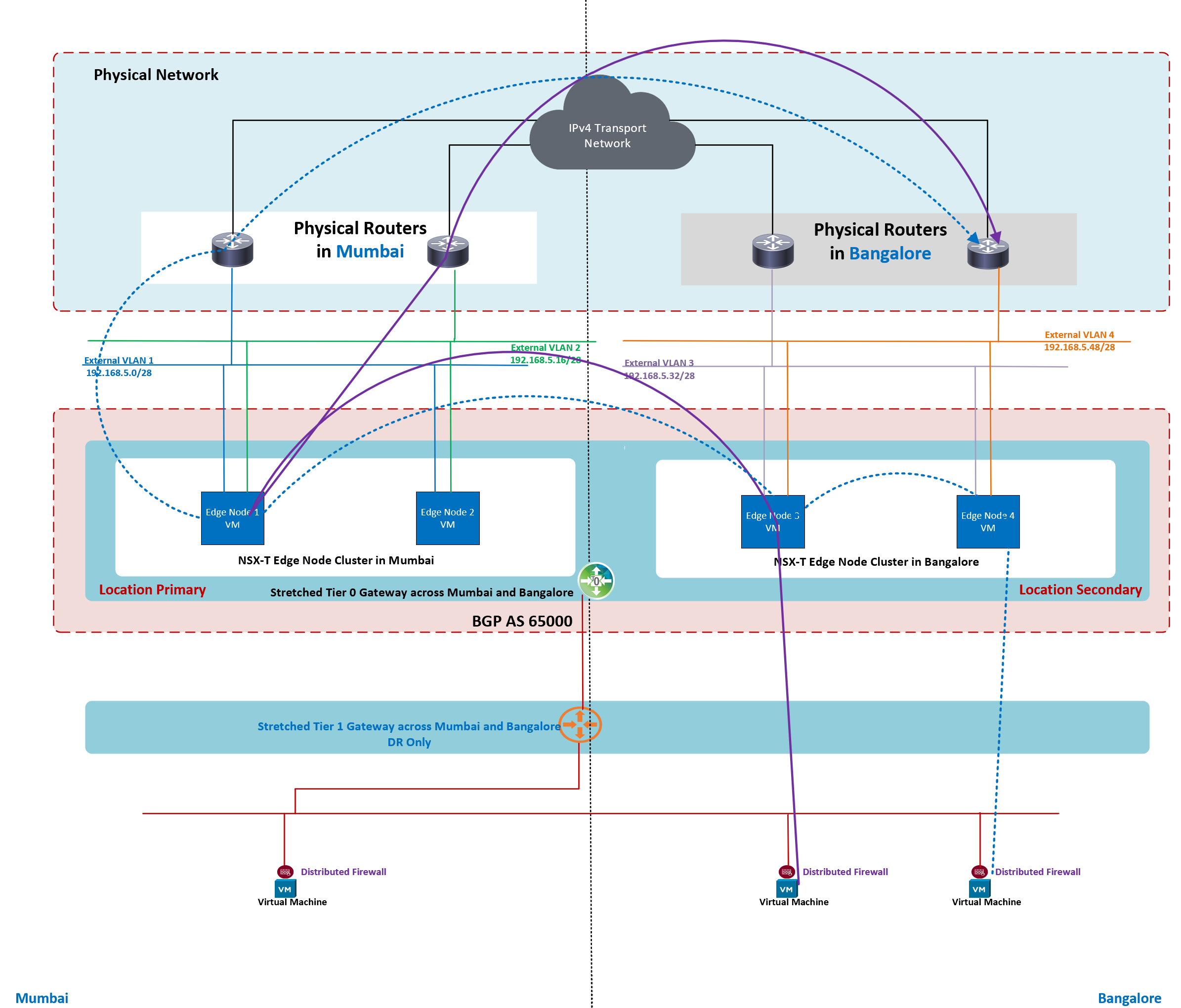
How segment stretching works?

Above figure shows two stretched networks. Within a location, specific edge offers segment stretching for a particular stretched network. As seen above, blue stretched segment is active on one edge in Mumbai and this blue stretched segment is active on one edge in Bangalore location. And the same logic is followed for segment stretching related to Orange stretched network. Above figure shows traffic flow between VMs connected to stretched network.
In one of my previous blogs, I have covered a topology where stretched Tier 0 Gateway is in Active-Active availability mode with locations as Primary & Secondary. But in that scenario BGP was used in underlay physical network. In this lab, we are replacing BGP in the physical network with OSPF.
This blog covers
- routing for stretched Tier 0 Gateway which spans two locations.
- Two locations are Mumbai and Bangalore
- Availability mode on Tier 0 Gateway is Active-Active
- Stretched Tier 0 Gateway has Mumbai as Primary Location and Bangalore as Secondary Location
- e-BGP between NSX edges and upstream physical routers
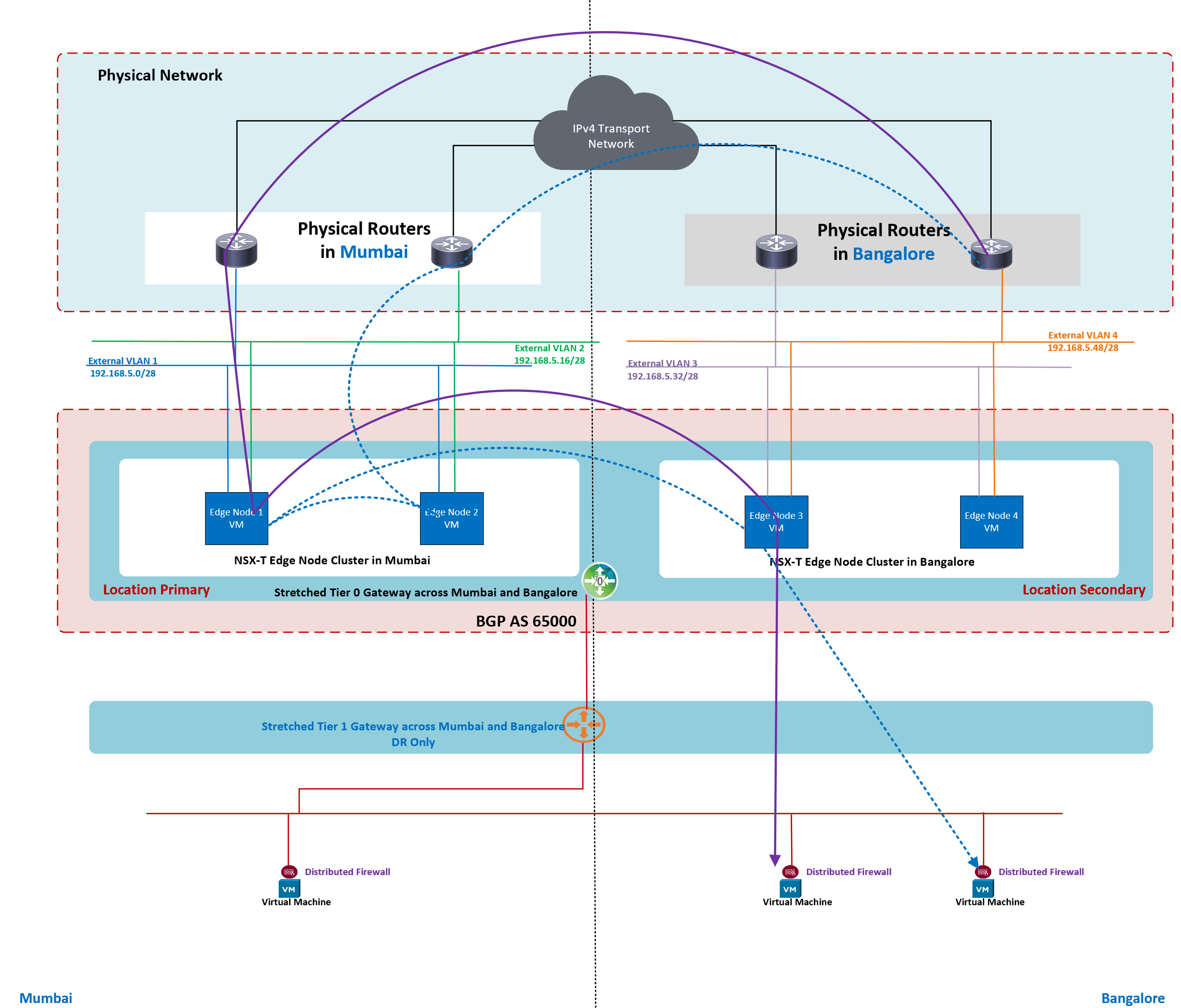
- OSPF backbone area 0 is configured on physical routers. All interfaces on the physical routers are placed in backbone area 0.

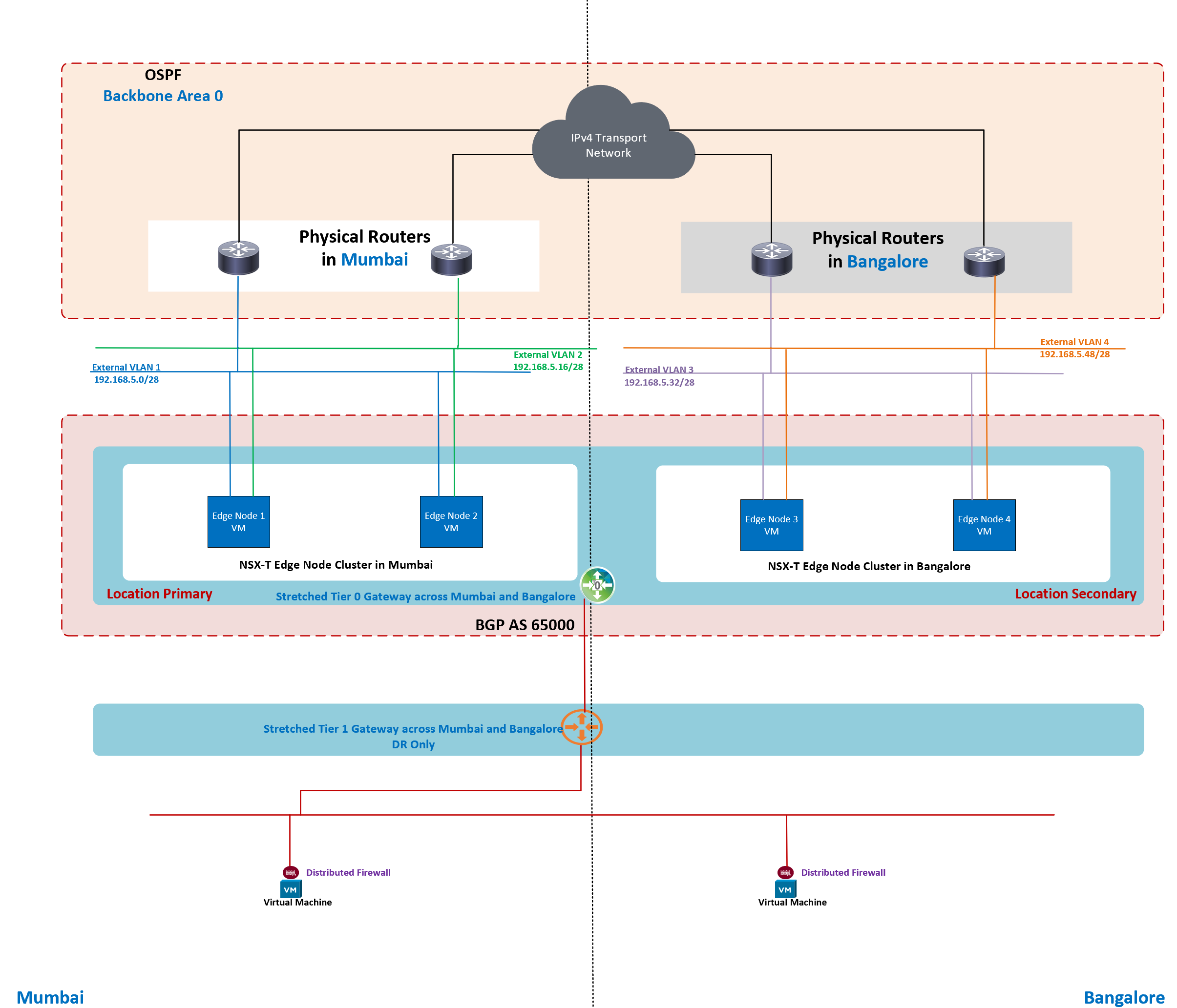
Above figure shows OSPF setup on the physical routers. In this lab, all the interfaces of all physical routers are placed in OSPF Area 0.

Above figure shows how BGP is setup in physical network and on NSX Tier 0 Gateway. e-BGP is in use between NSX edges and upstream physical routers. Physical routers will advertise default route towards NSX edges on a per BGP neighbor basis.
In this lab setup, I have prepared NSX Fabric in both locations. There is no standby Global Manager in this lab. For production setup, it is a must to deploy standby Global Manager.
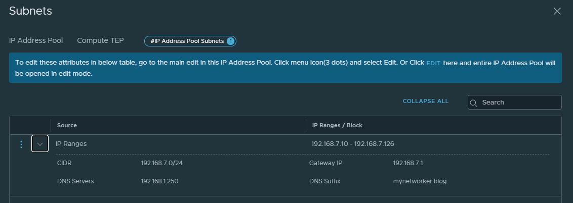
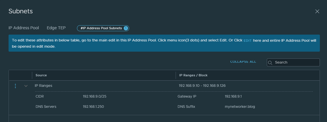
There are site local subnets for host TEP, edge TEP, edge RTEP, edge uplinks
There is NSX local manager in both the locations.
We need to define IP pools on the local NSX manager for host TEP, edge TEP and edge RTEP interfaces.

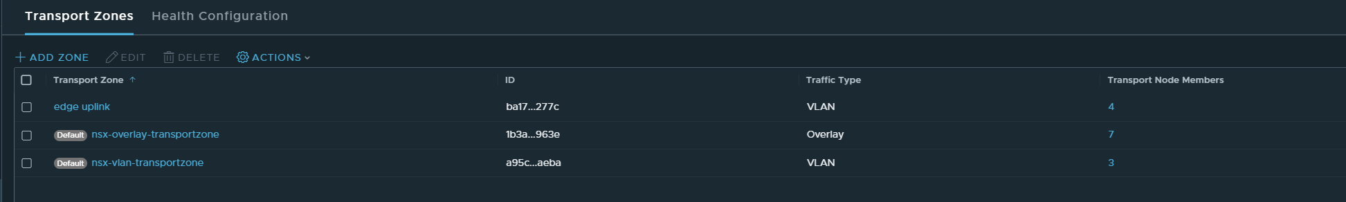
Besides the default transport zones, edge uplink transport zone has been configured. This transport zone is used to configure uplinks on NSX edges.
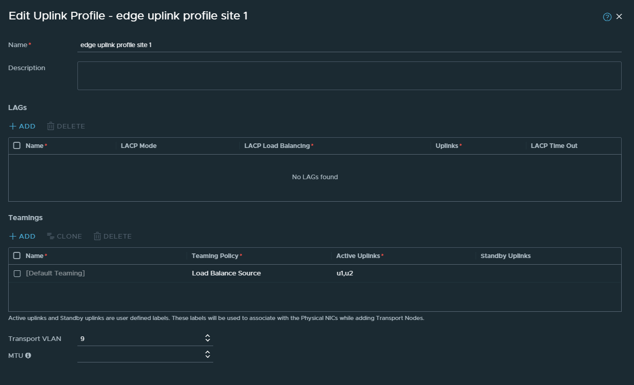
We need to configure uplink profiles for:
- Hosts
- Edges

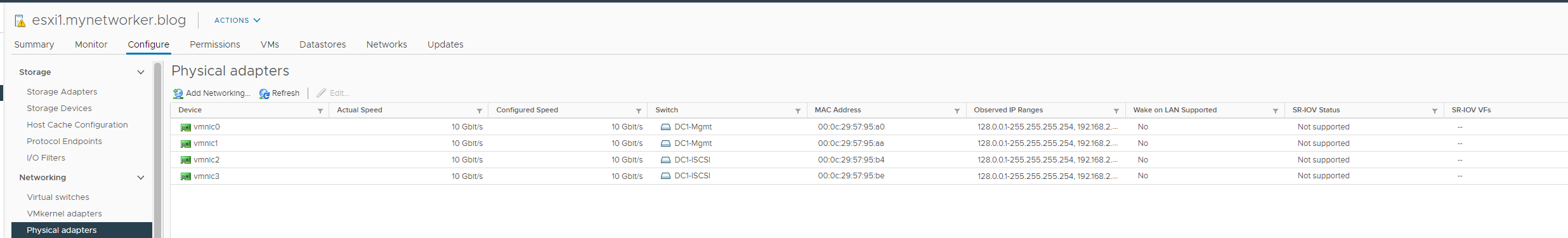
Each server has 4 pnics and there are two VDS’ per cluster.
- One VDS for handling ESXi management, vmotion, NSX traffic
- Second VDS for storage traffic.
Next configure Transport Node Profile which will be attached to cluster. You can have Transport Node Profile on a cluster basis.
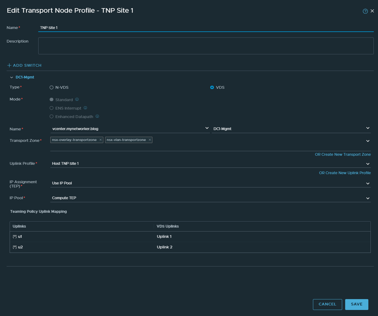
Using this transport node profile, servers are prepared for NSX.

Next edge VMs are deployed and configured for NSX.
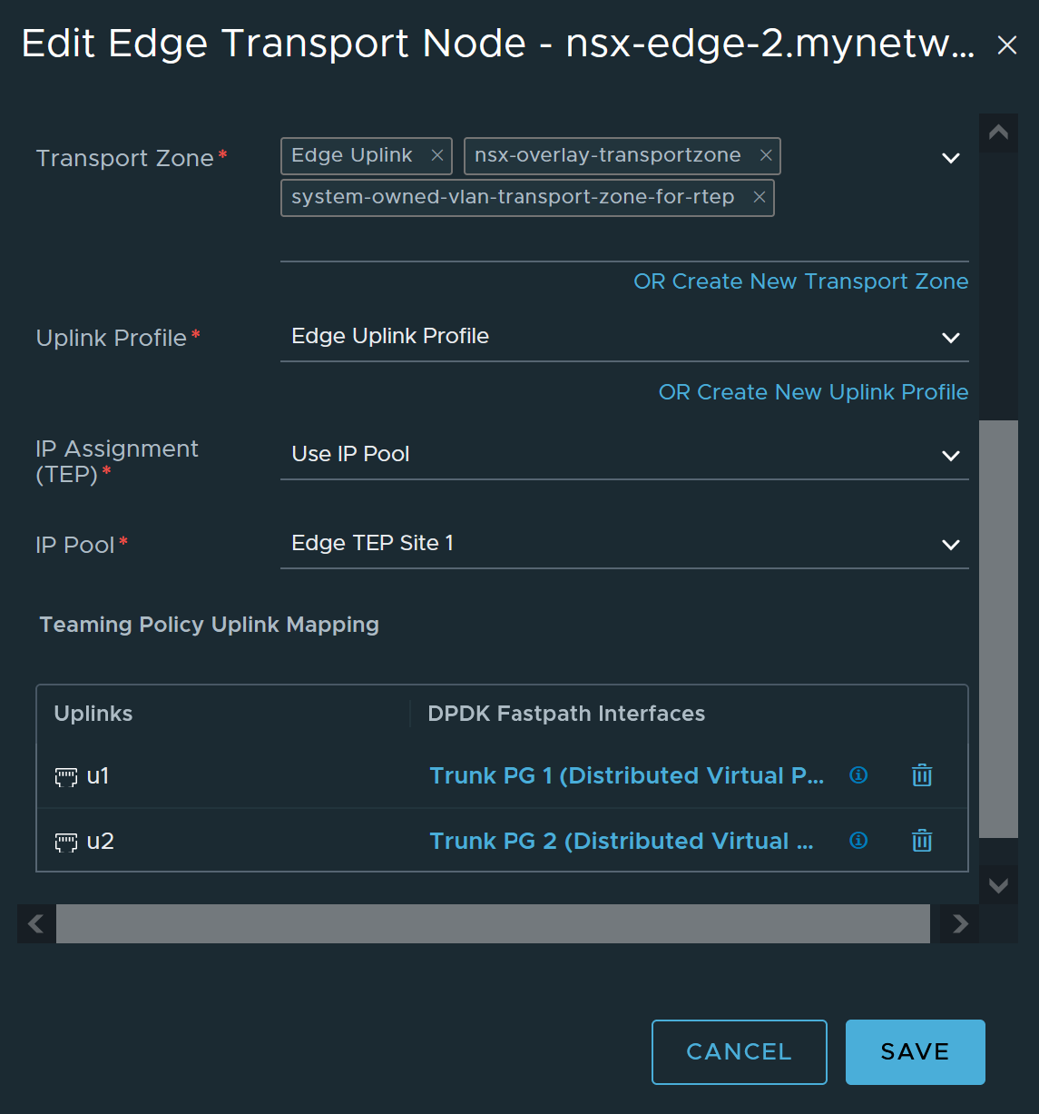
Two edges have been deployed and edge cluster is created out of those edges.

With this, NSX fabric in Mumbai has been configured.
The above steps are to be followed to prepare NSX fabric in Bangalore location as well.
Next deploy NSX-T Global Managers, add locations and configure RTEP interfaces on edges.
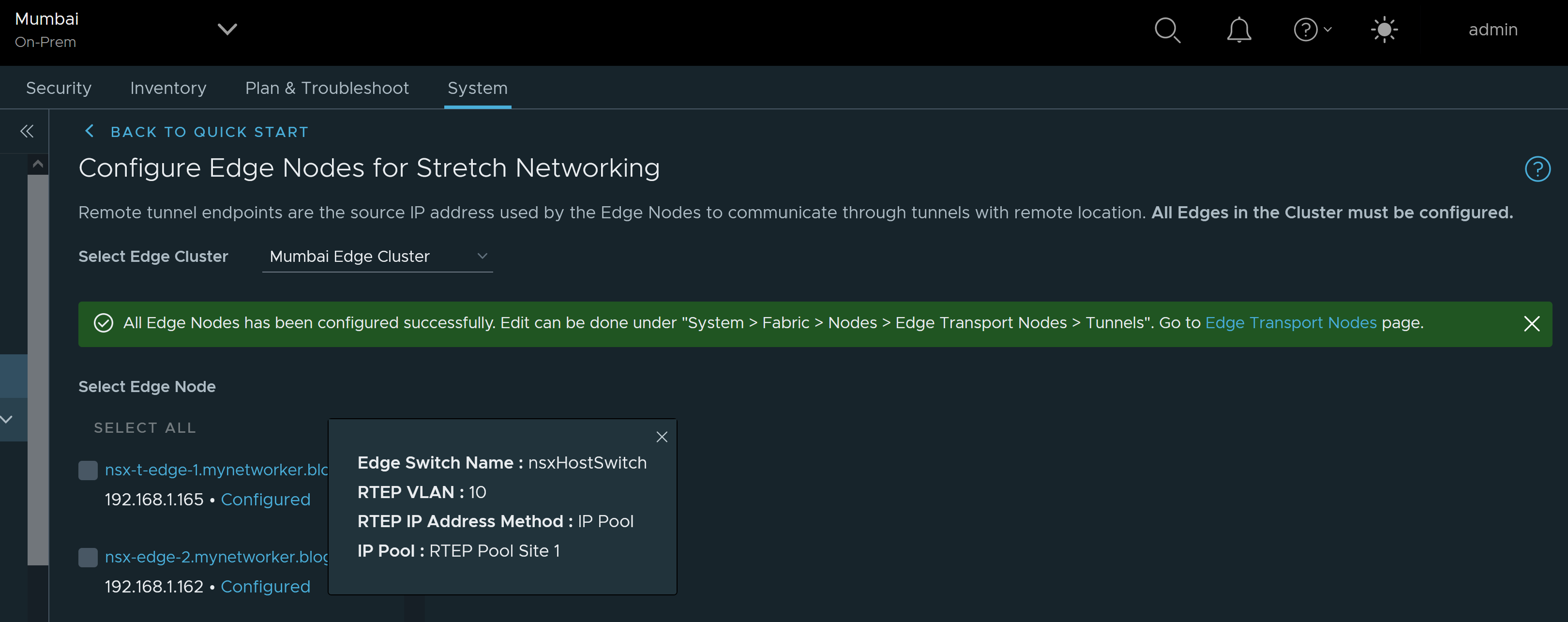
RTEP config has to be done on edges of both locations.
Next, we will login to NSX-T Active Global Manager and configure segments to be used for stretched Tier 0 Gateway uplink interfaces.

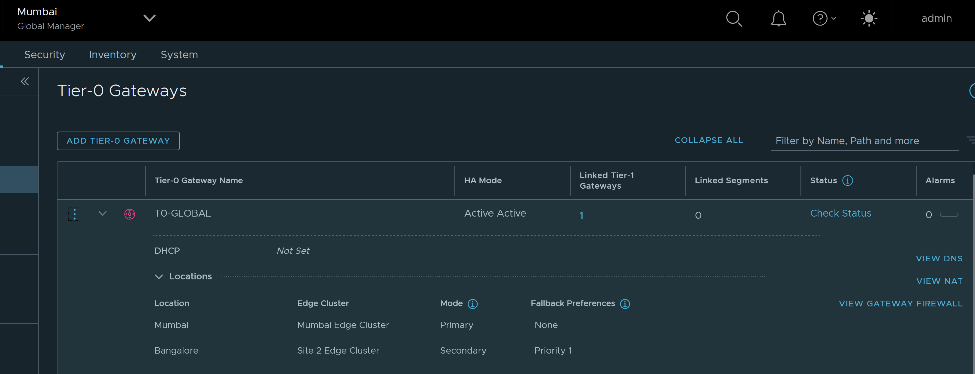
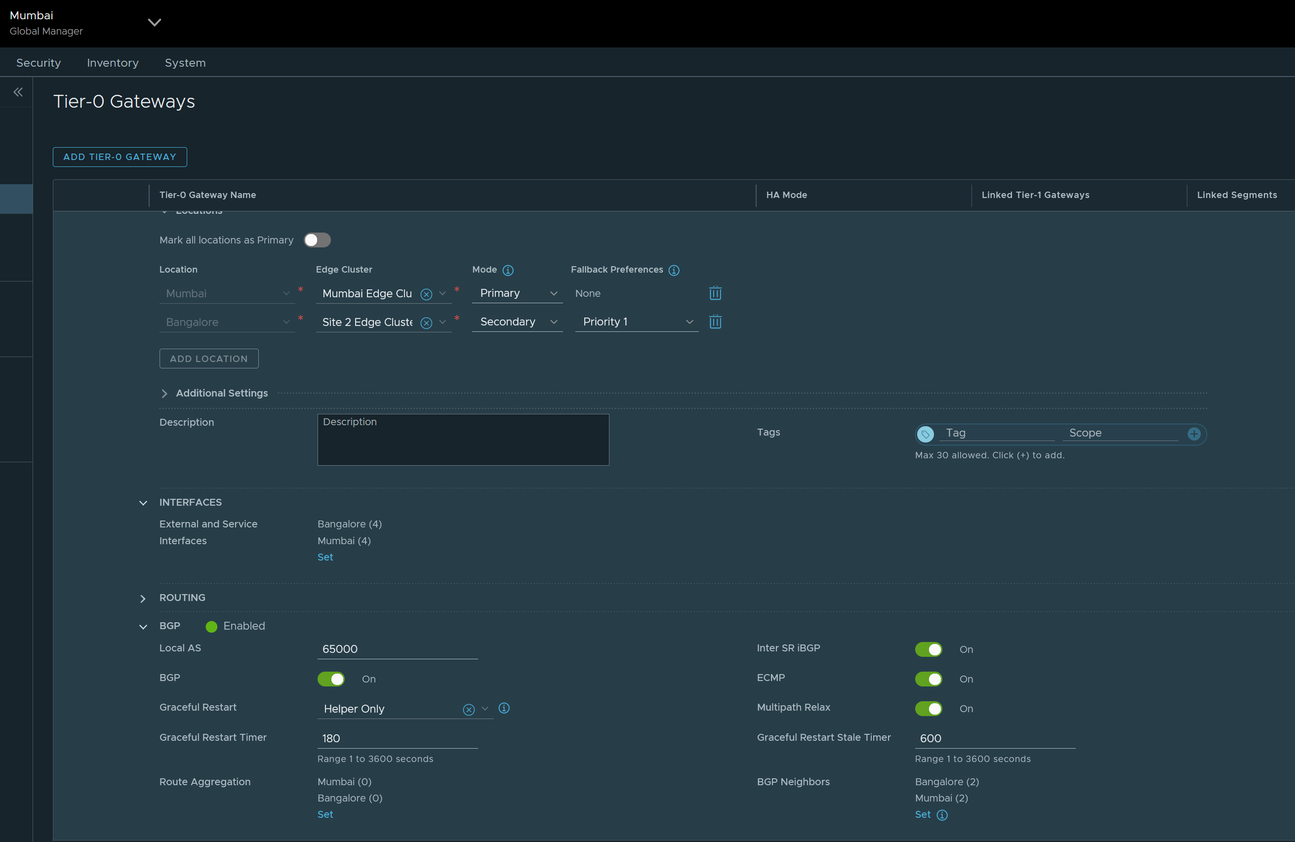
We will configure stretched Tier 0 Gateway and specify
- Mumbai as Primary Location
- Bangalore as Secondary Location
- Availability mode as Active-Active
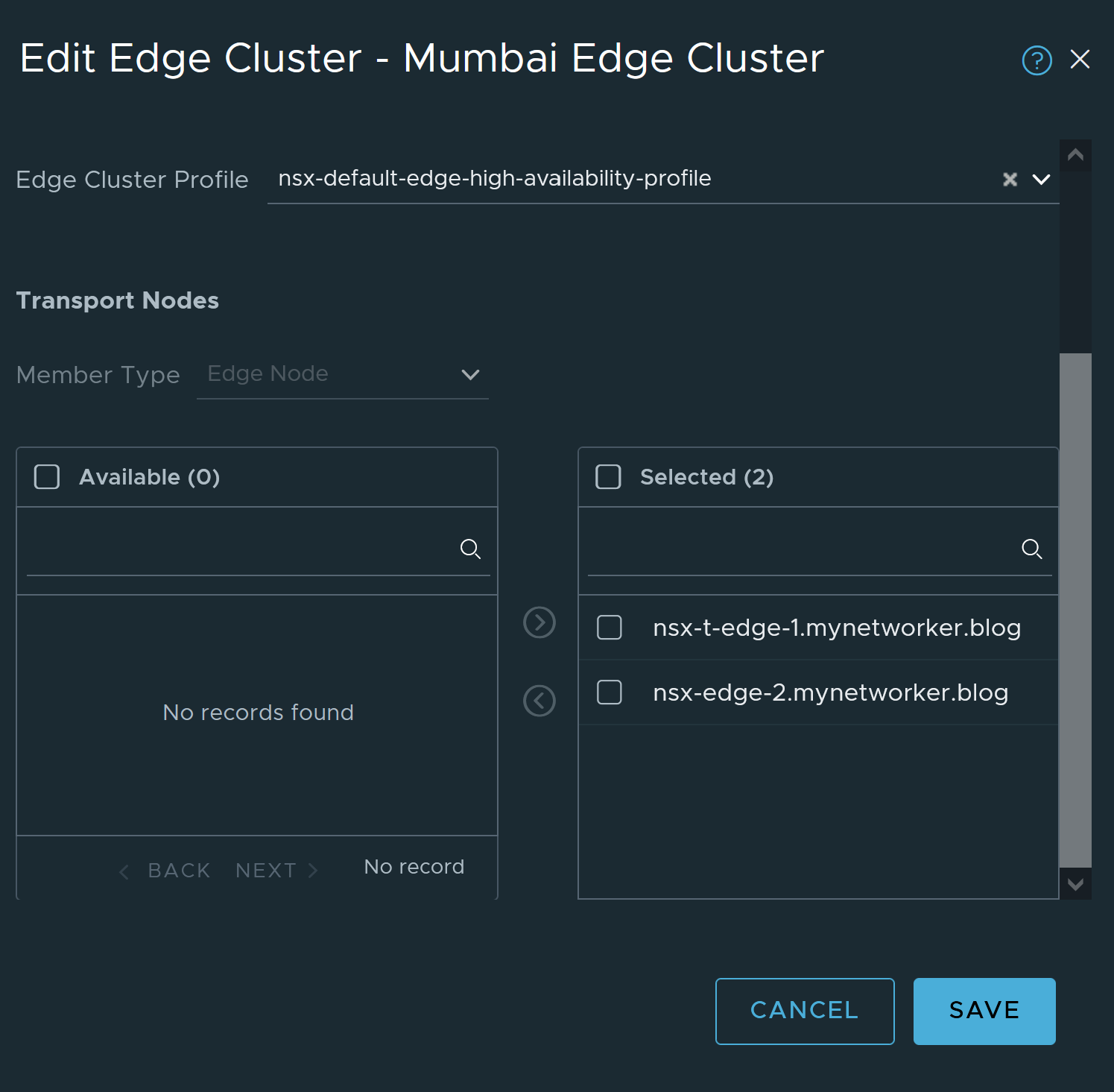
- Specify edge cluster for each location
Configure Layer 3 interfaces on stretched Tier 0 Gateway
For each interface specify:
- Location
- IP Address
- Connected segment
- Edge Node

Configure BGP
- Specify local AS number for the stretched Tier 0 Gateway
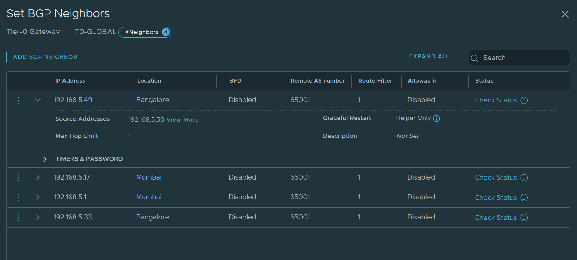
Configure BGP peers. For each peer specify
- Peer IP address
- Location
- Remote BGP AS number
- Source addresses for BGP peering
Enable redistribution on Tier 0 Gateway for Mumbai location only. We will not enable route redistribution for secondary location Bangalore.
Redistribute connected interfaces as shown below. As a result, NSX prefixes will be advertised via primary location Mumbai only.


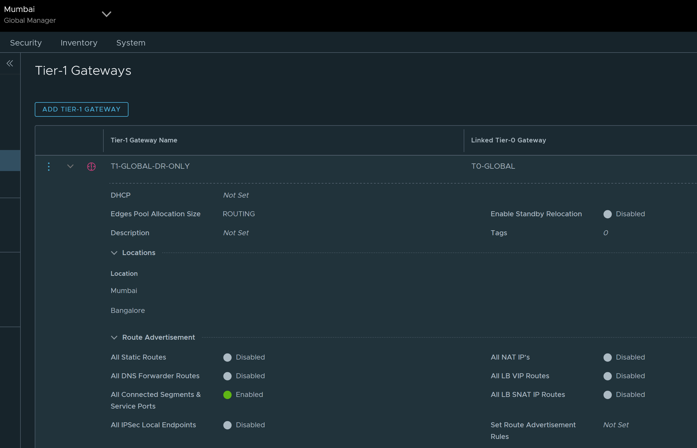
Next configure stretched T1, connect it to Tier 0 Gateway and advertise connected networks.
Here Tier 1 Gateway is DR only Tier 1 Gateway which is not connected to any edge cluster.
In this lab, there are no stateful services running on Tier 1 Gateway but they can be enabled based on specific requirement.
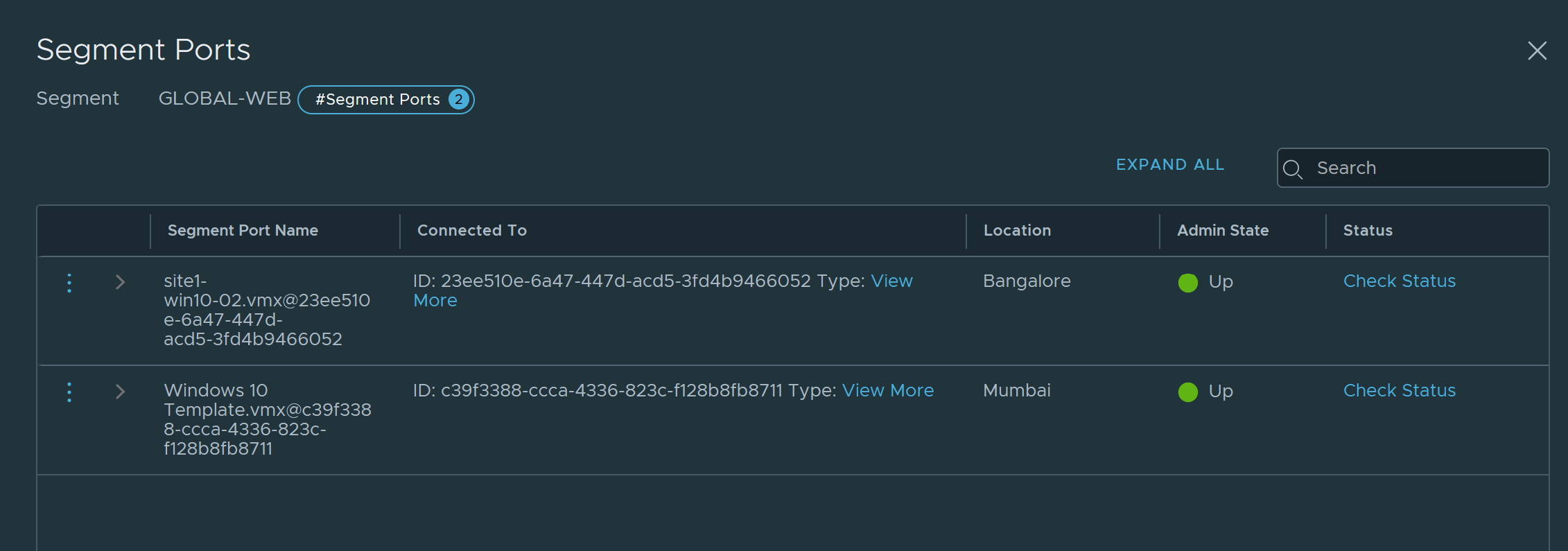
Next configure overlay network / segment which is attached to Tier 1 Gateway.
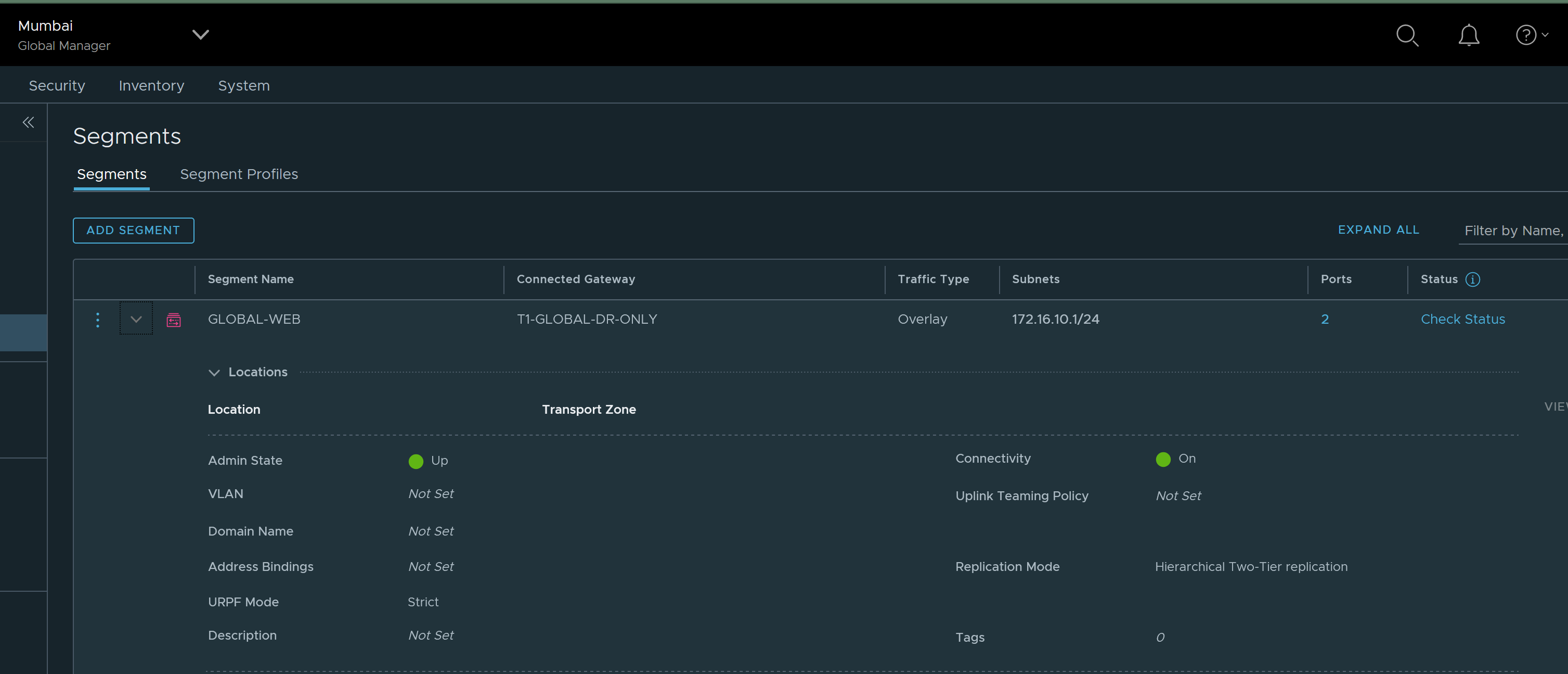
Next from vsphere client, use this overlay network on appropriate VMs.
Validation
Traffic flows
BGP routes on edges
Here the key point is that edges in Bangalore location do not advertise NSX routes because redistribution is disabled from Bangalore location.

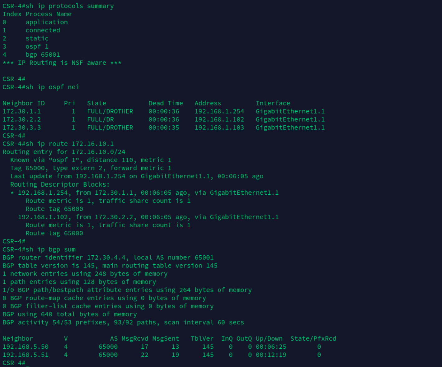
If we check the route for NSX prefix 172.16.10.0/24 on physical router in Bangalore location, next hop is towards physical routers in primary location Mumbai

172.30.1.1 is loopback interface of physical router 1 in Mumbai location
172.30.2.2 is loopback interface of physical router 2 in Mumbai location.


VM in Bangalore with IP 172.16.10.3 can reach below loopbacks:
172.30.1.1 on physical router 1 in Mumbai location.
172.30.2.2 on physical router 2 in Mumbai location.
172.30.3.3 on physical router 1 in Bangalore location.
172.30.4.4 on physical router 2 in Bangalore location.
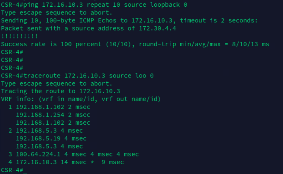
Physical router 2 in Bangalore location can reach VM in Bangalore location.
Disaster Recovery:
Upon complete failure of primary location, as part of disaster recovery:
a. Global manager in secondary location will be made as active. Data plane recovers automatically in case stretched T0 is Active/Active and Tier 1 Gateway is DR only gateway.
b. Ensure NSX routes are redistributed from secondary location.
